Table of Contents
Advertisement
Quick Links
BCE
OM‐01224‐10
August 6, 1984
Rev. C 09‐10‐2013
INSTALLATION, OPERATION,
AND MAINTENANCE MANUAL
WITH PARTS LIST
0 SERIES PUMP
MODEL
06B3-B
THE GORMAN‐RUPP COMPANY D MANSFIELD, OHIO
www.grpumps.com
D
GORMAN‐RUPP OF CANADA LIMITED
ST. THOMAS, ONTARIO, CANADA
Printed in U.S.A.
e
1984 The Gorman‐Rupp Company
Advertisement
Table of Contents

Related Manuals for GORMAN-RUPP PUMPS 06B3-B


Summary of Contents for GORMAN-RUPP PUMPS 06B3-B
- Page 1 August 6, 1984 Rev. C 09‐10‐2013 INSTALLATION, OPERATION, AND MAINTENANCE MANUAL WITH PARTS LIST 0 SERIES PUMP MODEL 06B3-B THE GORMAN‐RUPP COMPANY D MANSFIELD, OHIO www.grpumps.com GORMAN‐RUPP OF CANADA LIMITED ST. THOMAS, ONTARIO, CANADA Printed in U.S.A. 1984 The Gorman‐Rupp Company...
- Page 2 Register your new Gorman‐Rupp pump online at www.grpumps.com Valid serial number and e‐mail address required. RECORD YOUR PUMP MODEL AND SERIAL NUMBER Please record your pump model and serial number in the spaces provided below. Your Gorman‐Rupp distributor needs this information when you require parts or service. Pump Model: Serial Number:...
-
Page 3: Table Of Contents
TABLE OF CONTENTS INTRODUCTION ..........PAGE I - 1 SAFETY ‐... - Page 4 TABLE OF CONTENTS (continued) PUMP MAINTENANCE AND REPAIR ‐ SECTION E ....PAGE E - 1 STANDARD PERFORMANCE CURVE ........PAGE E - 1 PARTS LISTS: Pump End Assembly...
-
Page 5: Introduction
0 SERIES OM-01224 INTRODUCTION Thank You for purchasing a Gorman‐Rupp pump. The following are used to alert maintenance per Read this manual carefully to learn how to safely sonnel to procedures which require special atten install and operate your pump. Failure to do so tion, to those which could damage equipment, and could result in personal injury or damage to the to those which could be dangerous to personnel:... -
Page 6: Safety - Section A
0 SERIES OM-01224 SAFETY ‐ SECTION A This information applies to 0 Series ba sic pumps. Gorman‐Rupp has no con trol over or particular knowledge of the power source which will be used. Refer This pump is designed to handle petro to the manual accompanying the power leum products or other clean liquids source before attempting to begin oper... - Page 7 OM-01224 0 SERIES tional Electric Code and all local codes. If there is a conflict between the instruc tions in the manual accompanying the unit and the National Electric Code or Do not operate the pump without the the applicable local code, the National shields and/or guards in place over the or local code shall take precedence.
- Page 8 0 SERIES OM-01224 Never run this pump backwards. Be cer Pumps and related equipment must be in tain that rotation is correct before fully stalled and operated according to all na engaging the pump. tional, local and industry standards. SAFETY PAGE A - 3...
-
Page 9: Installation - Section B
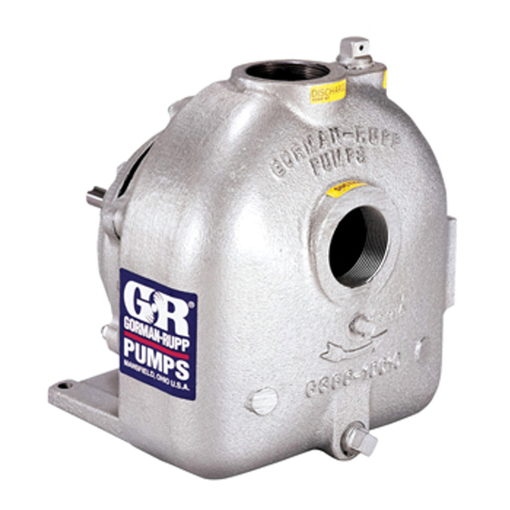
See Figure 1 for the approximate physical dimen some of the information such as mounting, line sions of this pump. OUTLINE DRAWING Figure 1. Pump Model 06B3-B INSTALLATION PAGE B - 1... -
Page 10: Preinstallation Inspection
OM-01224 0 SERIES PREINSTALLATION INSPECTION damage to the pump or components can occur if proper lifting procedures The pump assembly was inspected and tested be are not observed. Make certain that fore shipment from the factory. Before installation, hoists, chains, slings or cables are in inspect the pump for damage which may have oc... -
Page 11: Line Configuration
0 SERIES OM-01224 Line Configuration Strainers If a strainer is furnished with the pump, be certain Keep suction and discharge lines as straight as to use it; any spherical solids which pass through a possible to minimize friction losses. Make mini strainer furnished with the pump will also pass mum use of elbows and fittings, which substan... -
Page 12: Suction Line Positioning
OM-01224 0 SERIES Suction Line Positioning The pipe submergence required may be reduced by installing a standard pipe increaser fitting at the The depth of submergence of the suction line is end of the suction line. The larger opening size will critical to efficient pump operation. -
Page 13: Alignment
0 SERIES OM-01224 enough to prevent clogging, but not so large as to between the driving and the driven shafts. Refer to affect pump discharge capacity. the coupling manufacturer's service literature. Align spider insert type couplings by using calipers to measure the dimensions on the circumference ALIGNMENT of the outer ends of the coupling hub every 90_. -
Page 14: Drive Belt Tensioning
OM-01224 0 SERIES the sides of the pulleys to ensure that the pulleys DRIVE BELT TENSIONING are properly aligned (see Figure 5). In drive sys tems using two or more belts, make certain that the General Rules of Tensioning belts are a matched set; unmatched sets will cause accelerated belt wear. -
Page 15: Operation - Section C
OM-01224 0 SERIES OPERATION - SECTION C Review all SAFETY information in Section A. coming liquid to evacuate the air. After the pump and piping system have completely filled, evacu Follow the instructions on all tags, labels and ate any remaining air pockets in the pump or suc decals attached to the pump. -
Page 16: Operation
OM-01224 0 SERIES ature supplied with the motor for specific instruc Overheating can occur if operated with the valves tions. in the suction or discharge lines closed. Operating against closed valves could bring the liquid to a boil, build pressure, and cause the pump to rup OPERATION ture or explode. -
Page 17: Stopping
OM-01224 0 SERIES Shut off the pump. The vacuum gauge reading will normal for bearings, and they can operate safely to immediately drop proportionate to static suction at least 180_F (82_C). lift, and should then stabilize. If the vacuum reading Checking bearing temperatures by hand is inaccu... -
Page 18: Troubleshooting - Section D
OM-01224 0 SERIES TROUBLESHOOTING - SECTION D Review all SAFETY information in Section A. Before attempting to open or service the pump: 1. Familiarize yourself with this manual. 2. Disconnect or lock out the power source to ensure that the pump will remain inoperative. - Page 19 OM-01224 0 SERIES TROUBLE POSSIBLE CAUSE PROBABLE REMEDY Impeller or other wearing parts worn Replace worn or damaged parts. PUMP STOPS OR FAILS TO DELIVER or damaged. Check that impeller is properly RATED FLOW OR centered and rotates freely. PRESSURE (cont.) Impeller clogged.
-
Page 20: Preventive Maintenance
OM-01224 0 SERIES PREVENTIVE MAINTENANCE equipped) between regularly scheduled inspec tions can indicate problems that can be corrected Since pump applications are seldom identical, and before system damage or catastrophic failure oc pump wear is directly affected by such things as curs. - Page 21 PUMP MAINTENANCE AND REPAIR ‐ SECTION E MAINTENANCE AND REPAIR OF THE WEARING PARTS OF THE PUMP WILL MAINTAIN PEAK OPERATING PERFORMANCE. STANDARD PERFORMANCE FOR PUMP MODEL 06B3-B Based on 70_F (21_C) clear water at sea level Contact the Gorman‐Rupp Company to verify per...
- Page 22 OM-01224 0 SERIES PARTS PAGE SECTION DRAWING Figure 1. Pump Model 06B3-B PAGE E - 2 MAINTENANCE & REPAIR...
- Page 23 0 SERIES OM-01224 PARTS LIST Pump Model 06B3-B (From S/N 806819 Up) If your pump serial number is followed by an “N”, your pump is NOT a standard production model. Contact the Gorman‐Rupp Company to verify part numbers. ITEM PART NAME...
- Page 24 OM-01224 0 SERIES PUMP AND SEAL DISASSEMBLY 4. Check the temperature before opening any covers, plates, or AND REASSEMBLY plugs. Review all SAFETY information in Section A. 5. Close the suction and discharge valves. Follow the instructions on all tags, label and de 6.
- Page 25 0 SERIES OM-01224 Remove the suction and discharge lines. Remove Apply oil to the sleeve and work it up under the rub the nuts (35) and use a suitable hoist and sling to ber bellows. Slide the rotating portion of the seal off separate the pump casing and gasket (8) from the the shaft sleeve.
- Page 26 OM-01224 0 SERIES Place a block of wood against the impeller end of The bearing tolerances provide a tight press fit the shaft (22) and tap the shaft and assembled onto the shaft and a snug slip fit into the pedestal. bearings (24 and 32) from the bearing housing.
- Page 27 0 SERIES OM-01224 oughly filtered. ings should never be heated with a direct flame or directly on a hot plate. NOTE NOTE If a hot oil bath is used to heat the bearings, both the Position the inboard bearing (14) on the shaft as in oil and the container must be absolutely clean.
- Page 28 OM-01224 0 SERIES Seal Reassembly and Installation Handle the seal parts with extreme care to prevent damage. Be careful not to contaminate precision (Figures 1 and 3) finished faces; even fingerprints on the faces can shorten seal life. If necessary, clean the faces with a non‐oil based solvent and a clean, lint‐free tissue.
- Page 29 0 SERIES OM-01224 threads. Secure the seal plate to the pedestal with the round head machine screws (9). Subassemble the rotating element into the retainer and bellows. Lubricate the I.D. of the bellows with This seal is not designed for operation at water and slide this subassembly over the shaft temperatures above 160_F (71_C).
- Page 30 OM-01224 0 SERIES Refer to OPERATION, Section C, before putting NOTE the pump back into service. After the impeller has been properly positioned, check for free rotation. Correct any scraping bind ing before further reassembly. LUBRICATION Immobilize the impeller by inserting a bar between Seal Assembly the impeller vanes, being careful not to damage the vanes.
- Page 31 For U.S. and International Warranty Information, Please Visit www.grpumps.com/warranty or call: U.S.: 419-755-1280 International: +1-419-755-1352 For Canadian Warranty Information, Please Visit www.grcanada.com/warranty or call: 519-631-2870 THE GORMAN‐RUPP COMPANY D MANSFIELD, OHIO GORMAN‐RUPP OF CANADA LIMITED ST. THOMAS, ONTARIO, CANADA...
Need help?
Do you have a question about the 06B3-B and is the answer not in the manual?
Questions and answers