GORMAN-RUPP PUMPS 0 Series Installation, Operation, And Maintenance Manual With Parts List
Hide thumbs
Also See for 0 Series:

Related Manuals for GORMAN-RUPP PUMPS 0 Series


Summary of Contents for GORMAN-RUPP PUMPS 0 Series
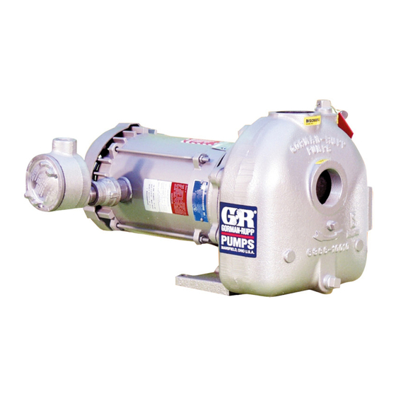
- Page 1 OM‐01231‐03 November 18, 2005 Rev. C 08‐07‐2019 INSTALLATION, OPERATION, AND MAINTENANCE MANUAL WITH PARTS LIST 0 SERIES PUMP MODEL 04A52-B GORMAN‐RUPP PUMPS www.grpumps.com 2005 Gorman‐Rupp Pumps Printed in U.S.A.
- Page 2 Register your new Gorman‐Rupp pump online at www.grpumps.com Valid serial number and e‐mail address required. RECORD YOUR PUMP MODEL AND SERIAL NUMBER Please record your pump model and serial number in the spaces provided below. Your Gorman‐Rupp distributor needs this information when you require parts or service. Pump Model: Serial Number:...
-
Page 3: Table Of Contents
TABLE OF CONTENTS INTRODUCTION ..........PAGE I - 1 SAFETY ‐... - Page 4 TABLE OF CONTENTS (continued) PUMP MAINTENANCE AND REPAIR ‐ SECTION E ....PAGE E - 1 STANDARD PERFORMANCE CURVE ........PAGE E - 1 PARTS LISTS: Pump End Assembly...
-
Page 5: Introduction
Gorman‐ Rupp pump. Immediate hazards which WILL result in This pump is an 0 Series, enclosed impeller, self‐ severe personal injury or death. These priming centrifugal model, designed with straight instructions describe the procedure re... -
Page 6: Safety - Section A
0 SERIES OM-01231 SAFETY ‐ SECTION A This information applies to 0 Series ba sic pumps. Gorman‐Rupp has no con trol over or particular knowledge of the power source which will be used. Refer This pump is designed to handle clear... - Page 7 OM-01231 0 SERIES Do not operate the pump against a Overheated pumps can cause severe closed discharge valve for long periods burns and injuries. If overheating of the of time. If operated against a closed dis pump occurs: charge valve, pump components will 1.
-
Page 8: Installation - Section B
0 SERIES OM-01231 INSTALLATION - SECTION B Review all SAFETY information in Section A. configuration, and priming must be tailored to the specific application. Since the pressure supplied Since pump installations are seldom identical, this to the pump is critical to performance and safety,... -
Page 9: Preinstallation Inspection
OM-01231 0 SERIES PREINSTALLATION INSPECTION damage to the pump or components can occur if proper lifting procedures The pump assembly was inspected and tested be are not observed. Make certain that fore shipment from the factory. Before installation, hoists, chains, slings or cables are in inspect the pump for damage which may have oc... -
Page 10: Line Configuration
0 SERIES OM-01231 Line Configuration install it with the stem horizontal to avoid air pock ets. Keep suction and discharge lines as straight as Strainers possible to minimize friction losses. Make mini mum use of elbows and fittings, which substan... -
Page 11: Suction Line In Sumps
OM-01231 0 SERIES suction inlets so that they are separated by a dis NOTE tance equal to at least 3 times the diameter of the The pipe submergence required may be reduced suction pipe. by installing a standard pipe increaser fitting at the end of the suction line. -
Page 12: Alignment
0 SERIES OM-01231 enough to prevent clogging, but not so large as to between the driving and the driven shafts. Refer to affect pump discharge capacity. the coupling manufacturer's service literature. Align spider insert type couplings by using calipers to measure the dimensions on the circumference ALIGNMENT of the outer ends of the coupling hub every 90_. -
Page 13: Drive Belt Tensioning
OM-01231 0 SERIES the sides of the pulleys to ensure that the pulleys are properly aligned (see Figure 5). In drive sys tems using two or more belts, make certain that the belts are a matched set; unmatched sets will cause Do not operate the pump without the accelerated belt wear. -
Page 14: Operation - Section C
OM-01231 0 SERIES OPERATION - SECTION C Review all SAFETY information in Section A. coming liquid to evacuate the air. After the pump and piping system have completely filled, evacu Follow the instructions on all tags, labels and ate any remaining air pockets in the pump or suc... -
Page 15: Operation
OM-01231 0 SERIES three phase wires to change direction. If rotation is Liquid Temperature And Overheating incorrect on a single‐phase motor, consult the liter The maximum liquid temperature for this pump is ature supplied with the motor for specific instruc... -
Page 16: Stopping
OM-01231 0 SERIES normal for bearings, and they can operate safely to inches (508,0 mm) or more of mercury. If it does at least 180_F (82_C). not, check for air leaks in the seal, gasket, or dis charge valve. Checking bearing temperatures by hand is inaccu... -
Page 17: Troubleshooting - Section D
OM-01231 0 SERIES TROUBLESHOOTING - SECTION D Review all SAFETY information in Section A. Before attempting to open or service the pump: 1. Familiarize yourself with this manual. 2. Disconnect or lock out the power source to ensure that the pump will remain inoperative. - Page 18 OM-01231 0 SERIES TROUBLE POSSIBLE CAUSE PROBABLE REMEDY PUMP STOPS OR Impeller or other wearing parts worn Replace worn or damaged parts. FAILS TO DELIVER or damaged. Check that impeller is properly RATED FLOW OR centered and rotates freely. PRESSURE (cont.) Impeller clogged.
-
Page 19: Preventive Maintenance
OM-01231 0 SERIES PREVENTIVE MAINTENANCE equipped) between regularly scheduled inspec tions can indicate problems that can be corrected Since pump applications are seldom identical, and before system damage or catastrophic failure oc pump wear is directly affected by such things as curs. - Page 20 0 SERIES OM-01231 PUMP MAINTENANCE AND REPAIR ‐ SECTION E MAINTENANCE AND REPAIR OF THE WEARING PARTS OF THE PUMP WILL MAINTAIN PEAK OPERATING PERFORMANCE. STANDARD PERFORMANCE FOR PUMP MODEL 04A52-B Based on 70_F (21_C) clear water at sea level Contact the Gorman‐Rupp Company to verify per...
- Page 21 OM-01231 0 SERIES PARTS PAGE ILLUSTRATION Ì Ì Ç Ç Ç Ì Ì Î Î Î Î Î Î Ï Ï Î Î Î Î Ç Ç Ç Î Î Î Î Î Î Î Î Î Î Î Î Î Î Î...
- Page 22 0 SERIES OM-01231 PARTS LIST Pump Model 04A52-B (From S/N 1326393 Up) If your pump serial number is followed by an “N”, your pump is NOT a standard production model. Contact the Gorman‐Rupp Company to verify part numbers. ITEM PART NAME...
- Page 23 OM-01231 0 SERIES PUMP AND SEAL DISASSEMBLY AND REASSEMBLY Review all SAFETY information in Section A. Before attempting to open or service the Follow the instructions on all tags, label and de pump: cals attached to the pump. 1. Familiarize yourself with this man...
- Page 24 0 SERIES OM-01231 Use caution not to damage the pump cas Use Only Genuine Gorman-Rupp re ing bore when removing the wear ring. placement parts. Failure to do so may cre ate a hazard and damage the pump or di...
- Page 25 OM-01231 0 SERIES To prevent damage during removal from Use caution not to damage the seal plate the shaft, it is recommended that bearings bore when removing the wear ring. be cleaned and inspected in place. It is strongly recommended that the bearings Shaft And Bearing Removal And Disassembly be replaced any time the shaft and bear...
- Page 26 0 SERIES OM-01231 Shaft And Bearing Reassembly And Heat the bearings to a uniform temperature no Installation higher than 250_F (120_C), and slide the bearings onto the shaft, one at a time, until they are fully Clean the pedestal, shaft and all component parts seated.
- Page 27 OM-01231 0 SERIES the bearing. Be careful not to cut the oil seal lip on precautions printed on solvent contain the shaft keyway. Be sure the machine screws in ers. the bearing retainer are positioned horizontally in The seal is not normally reused because wear pat...
- Page 28 0 SERIES OM-01231 ROTATING RETAINER ELEMENT SPRING O‐RING STATIONARY SEAT IMPELLER IMPELLER SHAFT SHAFT SLEEVE IMPELLER ADJUSTING SHIMS SEAL PLATE BELLOWS Figure 2. Seal Assembly Carefully slide the assembled seal plate and sta tionary seal element over the shaft. Use caution not to nick or damage the stationary seat.
- Page 29 OM-01231 0 SERIES To verify the impeller positioning, measure the impeller location (dimension E). Add or remove im pump casing and impeller as shown in Figure 3. peller adjusting shims (24) until dimension E is ob Use these measurements to calculate the required tained.
- Page 30 0 SERIES OM-01231 Refer to OPERATION, Section C, before putting NOTE the pump back into service. The white reflector in the sight gauge must be posi tioned horizontally to provide proper drainage. LUBRICATION Under normal conditions, drain the bearing hous...
- Page 31 For Warranty Information, Please Visit www.grpumps.com/warranty or call: U.S.: 419-755-1280 Canada: 519-631-2870 International: +1-419-755-1352 GORMAN‐RUPP PUMPS...
Need help?
Do you have a question about the 0 Series and is the answer not in the manual?
Questions and answers