GORMAN-RUPP PUMPS 0 Series Installation, Operation, And Maintenance Manual With Parts List
Hide thumbs
Also See for 0 Series:

Related Manuals for GORMAN-RUPP PUMPS 0 Series


Summary of Contents for GORMAN-RUPP PUMPS 0 Series
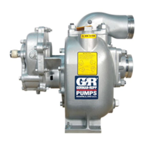
- Page 1 OM‐03756-02 January 11, 1993 Rev. C 09‐27‐19 INSTALLATION, OPERATION, AND MAINTENANCE MANUAL WITH PARTS LIST 0 SERIES PUMP MODEL 03H1-GR /S2 GORMAN‐RUPP PUMPS www.grpumps.com 1993 Gorman‐Rupp Pumps Printed in U.S.A.
- Page 2 Register your new Gorman‐Rupp pump online at www.grpumps.com Valid serial number and e‐mail address required. RECORD YOUR PUMP MODEL AND SERIAL NUMBER Please record your pump model and serial number in the spaces provided below. Your Gorman‐Rupp distributor needs this information when you require parts or service. Pump Model: Serial Number:...
-
Page 3: Table Of Contents
TABLE OF CONTENTS INTRODUCTION ..........PAGE I - 1 SAFETY SECTION A... - Page 4 TABLE OF CONTENTS (continued) PUMP MAINTENANCE AND REPAIR SECTION E ....PAGE E - 1 PERFORMANCE CURVE ........... PAGE E - 1 PARTS LIST: Pump Model...
-
Page 5: Introduction
Gorman‐ Rupp pump. This pump is an 0 Series, enclosed impeller, cen trifugal model, with straight‐in suction and without Immediate hazards which WILL result in a suction check valve. -
Page 6: Safety Section A
0 SERIES OM‐03756 SAFETY - SECTION A This information applies to 0 Series power take‐off pumps. Refer to the man ual accompanying the power source be fore attempting to begin operation. Be certain proper safety practices are followed before operating or servicing Because pump installations are seldom the pump. - Page 7 OM-03756 0 SERIES to a boil, build pressure, and cause the pump casing to rupture or explode. Do not remove plates, covers, gauges, pipe plugs, or fittings from an over heated pump. Vapor pressure within the Overheating may produce dangerous pump can cause parts being disen...
-
Page 8: Installation - Section B
0 SERIES OM-03756 INSTALLATION - SECTION B Review all SAFETY information in Section A. coming pressure to 50% of the maximum permissi ble operating pressure as shown on the pump per Since pump installations are seldom identical, this formance curve (see Section E, Page 1). -
Page 9: Preinstallation Inspection
OM-03756 0 SERIES PREINSTALLATION INSPECTION e. If the pump and gearbox have been stored for more than 12 months, some of the compo nents or lubricants may have exceeded their The pump assembly was inspected and tested be maximum shelf life. These must be inspected fore shipment from the factory. -
Page 10: Suction Lines
0 SERIES OM-03756 use lifting equipment with appropriate capacity. If a strainer is not furnished with the pump, but is Drain the pump and remove all customer‐installed installed by the pump user, make certain that the equipment such as suction and discharge hoses... -
Page 11: Discharge Lines
OM-03756 0 SERIES recommended minimum submergence vs. veloc end of the suction line. The larger opening size will ity. reduce the inlet velocity. Calculate the required submergence using the following formula based on the increased opening size (area or diameter). -
Page 12: Alignment
0 SERIES OM-03756 ing angle should not exceed 15 degrees (see Fig ALIGNMENT ure 3). Check the direction of rotation of the PTO unit be fore starting the pump. The drive shaft must rotate in the direction shown on the body of the pump, gearbox, and/or decals, tags, and labels. -
Page 13: Suction And Discharge Piping
OM-03756 0 SERIES LUGS MUST BE IN LINE, REGARDLESS OF OPERATING ANGLE SHOWN BELOW LUG ALIGNMENT SHAFTS PARALLEL, ANGLES EQUAL SHAFTS NOT PARALLEL, ANGLES EQUAL Figure 3. Proper Installation And Alignment of Universal Assembly SUCTION AND DISCHARGE PIPING tors, related piping and safety accessories. Some of the accessories are available from Gorman‐... -
Page 14: Piping
0 SERIES OM-03756 SCHEMATIC SYSTEM USING EDUCTOR FOR DISPENSING AND FILLING Figure 4. Typical Installation Using Educator For Filling And Dispensing SCHEMATIC SYSTEM USING PUMP FOR DISPENSING AND FILLING Figure 5. Typical Installation Using Pump For Filling And Dispensing Piping... -
Page 15: Sealing
OM-03756 0 SERIES suction line to ensure an adequate supply of liquid Sealing to the pump. Since even a slight leak will affect priming, head, and capacity, especially when operating with a high suction lift, all connections in the suction line should be sealed with pipe dope to ensure an air... -
Page 16: Siphoning
0 SERIES OM-03756 Siphoning FDF valve to increase dispensing rates and im prove efficiency. An educator may also be used to Do not terminate the discharge line at a level lower collapse the tank service hose after the tank has than that of the liquid being pumped unless a si... -
Page 17: Operation - Section C
OM-03756 0 SERIES OPERATION - SECTION C Review all SAFETY information in Section A. Add liquid to the pump casing when: 1. The pump is being put into service for the Follow the instructions on all tags, labels and first time. -
Page 18: Drive
OM-03756 0 SERIES be damaged and performance adversely affected Liquid Temperature And Overheating by incorrect rotation. If pump performance is not within the specified limits (see the curve on Page The maximum liquid temperature for this pump is E-1), check the direction of rotation before further 160_ F (71_C). -
Page 19: Pump Vacuum Check
OM-03756 0 SERIES Pump Vacuum Check Since this pump does not have a suction check valve, the discharge line must be fitted with a check If the application involves a high discharge valve if a pump vacuum reading is to be taken. -
Page 20: Troubleshooting - Section D
0 SERIES OM-03756 TROUBLESHOOTING - SECTION D Review all SAFETY information in Section A. Before attempting to open or service the pump: 1. Familiarize yourself with this manual. 2. Switch off the vehicle ignition and re move the key, or take other precau... - Page 21 OM-03756 0 SERIES TROUBLE POSSIBLE CAUSE PROBABLE REMEDY Impeller or other wearing parts worn Replace worn or damaged parts. PUMP STOPS OR FAILS TO DELIVER or damaged. Check that impeller is properly cen RATED FLOW OR tered and rotates freely.
- Page 22 0 SERIES OM-03756 equipped) between regularly scheduled inspec PREVENTIVE MAINTENANCE tions can indicate problems that can be corrected Since pump applications are seldom identical, and before system damage or catastrophic failure oc pump wear is directly affected by such things as curs.
- Page 23 0 SERIES OM-03756 PUMP MAINTENANCE AND REPAIR ‐ SECTION E MAINTENANCE AND REPAIR OF THE WEARING PARTS OF THE PUMP WILL MAINTAIN PEAK OPERATING PERFORMANCE. STANDARD PERFORMANCE FOR PUMP MODEL 03H1-GR /S2 Based on 70_ F (21_ C) clear water corrected to Contact the Gorman‐Rupp Company to verify per...
- Page 24 OM-03756 0 SERIES ILLUSTRATION PARTS PAGE Figure 1. Pump Model 03H1-GR /S2 PAGE E - 2 MAINTENANCE & REPAIR...
- Page 25 0 SERIES OM-03756 PARTS LIST Pump Model 03H1-GR /S2 (From S/N 1010289 Up) If your pump serial number is followed by an “N”, your pump is NOT a standard production model. Contact the Gorman‐Rupp Company to verify part numbers. ITEM...
- Page 26 OM-03756 0 SERIES ILLUSTRATION Ç Ç Ç Ç Ì Ì Ì Ì DETAIL B Ç Ç Ç Ç Ç Ç Ç Ç Ç Ç Ç Ç Ç Ç Ç Ç Ç Ç Ç Ç Ç Ç Ç Ç Ç Ç Ç Ç Ç Ç...
- Page 27 0 SERIES OM-03756 PARTS LIST 44161-014 Gear Box Assembly ITEM PART PART NAME NUMBER WEAR RING 62ZL6 14000 PINION 8896 16020 OIL SEAL S1764 REDUCER PIPE BUSHING AP0602 15079 AIR VENT S1530 LOCK WASHER J06 15991 HEX HEAD CAP SCREW...
- Page 28 OM-03756 0 SERIES PUMP AND SEAL DISASSEMBLY 5. Close the suction and discharge valves. AND REASSEMBLY 6. Vent the pump slowly and cau tiously. Review all SAFETY information in Section A. 7. Drain the pump. Follow the instructions on all tags, label and de...
- Page 29 0 SERIES OM-03756 Impeller Removal (Figure 1) To loosen the impeller screw (11), immobilize the The pump assembly can be seriously drive shaft (11, Figure 2). Remove the impeller damaged if the cables or chains used to lift screw, lockwasher (10), and impeller washer (9).
- Page 30 OM-03756 0 SERIES Seal Reassembly and Installation Handle the seal parts with extreme care to prevent damage. Be careful not to contaminate precision (Figures 1 and 3) finished faces; even fingerprints on the faces can shorten seal life. If necessary, clean the faces with a Clean the seal cavity and shaft with a cloth soaked non‐oil based solvent and a clean, lint‐free tissue.
- Page 31 0 SERIES OM-03756 impeller or binding and/or excessive wear will result. Align the impeller and key (8) with the shaft key This seal is not designed for operation at way, and press the impeller onto the shaft until fully seated. Be sure the seal spring seats squarely...
- Page 32 OM-03756 0 SERIES Step 1 Step 2 Step 3 Figure 4. Centering Impeller Within Pump Casing Install the calculated thickness of pump casing GEARBOX DISASSEMBLY gaskets. Secure the pump casing to the seal plate (Figure 2) with the nuts (15).
- Page 33 0 SERIES OM-03756 sembled oil seal (13) off the shaft. Remove the cov shorten bearing life. Do not spin dry bear er plate gasket (9) and bearing adjusting shims ings. This may scratch the balls or races (18). Tie and tag the shims, or measure and record and cause premature bearing failure.
- Page 34 OM-03756 0 SERIES oil and the container must be absolutely clean. If tioned as shown in Figure 2. Press the oil seal into the oil has been previously used, it must be thor the seal plate until the inner side of the seal is just oughly filtered.
- Page 35 0 SERIES OM-03756 Add 1 ounce (29,5 ml) of Dow Corning `Molykoter LUBRICATION M Gear Guard' to the gearbox, then top off with ap proximately 2 ounces (59 ml) of premium quality, Seal Assembly multi‐purpose, extreme pressure gear lubricant with an SAE rating per the ambient temperatures The seal assembly is lubricated by the medium be...
- Page 36 For Warranty Information, Please Visit www.grpumps.com/warranty or call: U.S.: 419-755-1280 Canada: 519-631-2870 International: +1-419-755-1352 GORMAN‐RUPP PUMPS...
Need help?
Do you have a question about the 0 Series and is the answer not in the manual?
Questions and answers