Sign In
Upload
Download
Table of Contents
Contents
Add to my manuals
Delete from my manuals
Share
URL of this page:
HTML Link:
Bookmark this page
Add
Manual will be automatically added to "My Manuals"
Print this page
×
Bookmark added
×
Added to my manuals
Manuals
Brands
Beko Manuals
Water Filtration Systems
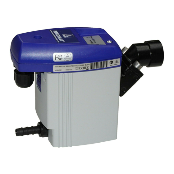
BEKOMAT 31U
Instructions for installation and operation manual
Beko BEKOMAT 31U Instructions For Installation And Operation Manual
Electronically level-controlled condensate drain for compressed-air plants.
Hide thumbs
Also See for BEKOMAT 31U
:
Instructions for installation and operation manual
(11 pages)
1
2
Table Of Contents
3
4
5
6
7
8
9
10
11
12
13
14
15
16
17
18
19
20
21
22
23
24
25
26
27
28
29
30
31
32
page
of
32
Go
/
32
Contents
Table of Contents
Troubleshooting
Bookmarks
Table of Contents
Table of Contents
Pictograms and Symbols
Safety Instructions
Proper Use
Exclusion from the Scope of Application
Technical Data
Electrical Data
Dimension Drawing
Climate Zones and Performance Data
Function
Installation
Electrical Installation
Inspection and Maintenance
Troubleshooting and Fault Elimination
Elements and Components
Recommended Spare Parts
Accessories
Declaration of Conformity
Advertisement
Quick Links
1
Table of Contents
2
Pictograms and Symbols
3
Technical Data
4
Electrical Data
5
Function
6
Inspection and Maintenance
7
Troubleshooting and Fault Elimination
8
Elements and Components
Download this manual
EN - english
Instructions for installation and operation
Condensate drain
®
BEKOMAT
31U
(BM31U)
Table of
Contents
Previous
Page
Next
Page
1
2
3
4
5
Advertisement
Table of Contents
Need help?
Do you have a question about the BEKOMAT 31U and is the answer not in the manual?
Ask a question
Questions and answers
Related Manuals for Beko BEKOMAT 31U
Industrial Equipment Beko BEKOMAT 31U F Instructions For Installation And Operation Manual
(11 pages)
Water Filtration Systems Beko QWIK-PURE 200 Instructions For Installation And Operation Manual
Oil water separator (32 pages)
Water Filtration Systems Beko QWIK-PURE 200 Instruction Manual
(32 pages)
Water Filtration Systems Beko CLEARPOINT 3eco S040 Installation And Operation Manual
Coalescing filter (56 pages)
Water Filtration Systems Beko CLEARPOINT 3eco S040 Translation Of Original Installation And Operation Manual
Coalescence filter (56 pages)
Water Filtration Systems Beko CLEARPOINT 3eco S040 Original Installation And Operating Manual
Coalescing filter (60 pages)
Water Filtration Systems Beko BEKOMAT 14i Manual
(76 pages)
Water Filtration Systems Beko OWAMAT 2 Instructions For Installation And Operation Manual
Oil/water separator (25 pages)
Water Filtration Systems Beko OWAMAT 2 Instructions For Installation And Operation Manual
Oil water separator (24 pages)
Water Filtration Systems Beko ÖWAMAT 6 Instructions For Installation And Operation Manual
Oil water separator (24 pages)
Water Filtration Systems Beko OWAMAT 1 Instructions For Installation And Operation Manual
(12 pages)
Water Filtration Systems Beko CLEARPOINT L080 Instructions For Installation And Operation Manual
Filter with flanged connection (28 pages)
Water Filtration Systems Beko owamat 12 Instructions For Installation And Operation Manual
Oil-water separator (40 pages)
Water Filtration Systems Beko CLEARPOINT S040 Installation And Operation Manual
Water separator (56 pages)
Water Filtration Systems Beko OEWAMAT 6 Instructions For Installation And Operation Manual
(24 pages)
Water Filtration Systems Beko QWIK-PURE CS Installation And Operating Manual
(132 pages)
This manual is also suitable for:
Bm31u
Table of Contents
Save PDF
Print
Rename the bookmark
Delete bookmark?
Delete from my manuals?
Login
Sign In
OR
Sign in with Facebook
Sign in with Google
Upload manual
Upload from disk
Upload from URL


Need help?
Do you have a question about the BEKOMAT 31U and is the answer not in the manual?
Questions and answers