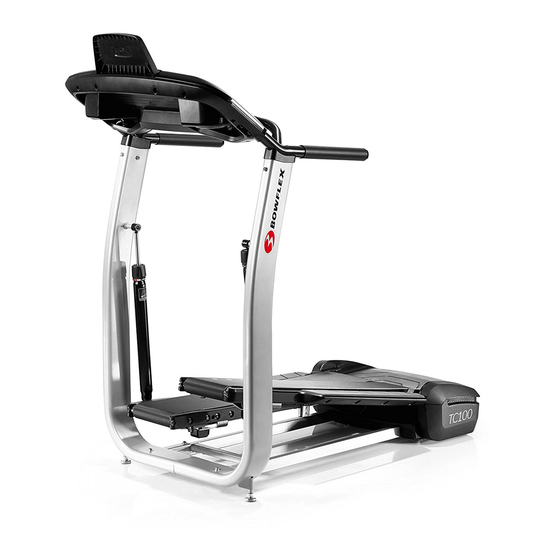
Bowflex TreadClimber TC100 Assembly & Owners Manual
Hide thumbs
Also See for TreadClimber TC100:
- User manual ,
- Service manual (107 pages) ,
- Troubleshooting manual (6 pages)


Need help?
Do you have a question about the TreadClimber TC100 and is the answer not in the manual?
Questions and answers