Table of Contents
Advertisement
Quick Links
Advertisement
Table of Contents

Related Manuals for 3DR Solo


Summary of Contents for 3DR Solo
- Page 1 Operation Manual...
- Page 2 3DR Support We’re here to help! If you have any questions about your Solo or if you need technical support, don’t hesitate to contact us. online: 3dr.com/support email: support@3dr.com call: +1 (858) 225-1414 (direct) +1 (855) 982-2898 (toll free in the US and Canada)
-
Page 3: Table Of Contents
Contents System Description System Overview Aircraft Overview Controller Overview Operating Parameters Autopilot Propulsion Electrical System Communication Setup In the Box Battery Controller Propellers Camera Safety Location Environmental Awareness Propellers Home Position Altitude & Safety Fence Emergency Procedures Power Management Flight Battery Controller 3.10 GPS Management... - Page 4 Figure 1.1.1: Solo System Context Diagram Figure 1.2.1: Solo Exterior Overview Figure 1.2.2: Solo Interior Overview Figure 1.3.1: Controller Schematic Diagram Figure 1.4.1: Solo Operating Parameters & Specifications Table Figure 1.5.1: Solo Onboard Sensors Table Figure 1.6.1: Motor Schematic Diagram Figure 1.6.2: Solo Motor Order Figure 1.7.1: Solo Electrical System...
-
Page 5: System Description
Solo. The “3DR Solo” app outputs a live video stream from Solo’s onboard camera to an Android or iOS device. The operator can use the app to view the live video with overlaid telemetry and access a simplified graphic interface for controlling Solo’s advanced functions. -
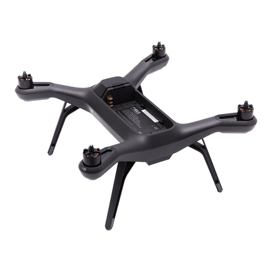
Page 6: Aircraft Overview
Motors and Propellers Solo’s arms are labelled one through four on the ends of the arms. Motors on arms #1 and #2 spin counterclockwise and use clockwise-tightening propellers with silver tops. Conversely, motors on arms #3 and #4 spin clockwise and use clockwise-tightening propellers with black tops. -
Page 7: Controller Overview
Twin dipole antenna in the legs #1 and #2 send and receive signals from the 3DR Link WiFi network. Mainboard Compass Antenna Figure 1.2.2: Solo Interior Overview 1.3 Controller Overview Mobile-Device Holder Mount an Android or iOS device to run the Solo app and effortlessly integrate the app into the controller’s operation flow. -
Page 8: Figure 1.3.1: Controller Schematic Diagram
The fly button lets you control Solo’s main flight functions: starting motors, auto-takeoff, auto-land, and activating manual flight. Return Home The return-home button allows you to end your flight automatically at any point by returning Solo to its original launch point and landing. Pause Button The pause bottom is Solo’s emergency air brake. -
Page 9: Operating Parameters
STM32F427 processor with 2 MB of flash memory and 256 KB of RAM. Combined with an array of CAN, I2C, SPI, PWM, and UART interfaces, Pixhawk 2 uses a suite of onboard sensors to calculate Solo’s orientation and motion in flight. -
Page 10: Propulsion
Figure 1.5.1: Solo Onboard Sensors Table Location Sensor Manufacturer / Part Number* Data Type Pixhawk 2 FMU Accelerometer InvenSense / MPU6000 Orientation Pixhawk 2 FMU Gyroscope InvenSense / MPU6000 Motion Pixhawk 2 FMU Magnetometer Honeywell / HMC 5983 Cardinal direction... -
Page 11: Electrical System
Solo Link, 3DR Solo GPS, and 3DR Solo Compass. These components have a two-way serial signal link with the mainboard to transfer data between them via the mainboard as a central hub. The LEDs on each arm of Solo are components of the ESCs and receive power and I2C signals via the ESCs. -
Page 12: Communication
3DR Link network and received by 3DR Controller Link which re-transmits the inputs to Solo over the 3DR Link network. The redirection of controls from the app is due to the improved range of the controller’s antennas. -
Page 13: Setup
(Keep in mind that flight time depends on payload, wind conditions, elevation, temperature, humidity, flying style and pilot skill, so the actual flight time may vary.) As a lithium polymer battery, the Solo Smart Battery requires specific handling practices to ensure safe operation and prevent accidents. For more information about battery safety, see section 20. -
Page 14: Figure 2.2.1: Charge Solo Battery
Powering To power Solo, insert the battery into Solo’s battery bay and slide the battery forward until it clicks into place. Press and hold the battery power button to turn on Solo. When Solo power on, the battery will display an LED animation and you will hear the startup tone. -
Page 15: Controller
You need to switch the controller battery for a new or upgraded controller battery. Upgraded controller batteries with double the capacity are available from store.3dr.com. In the case where you need to store the extra controller battery, store it in location where it will not come into contact with metal objects or other batteries. -
Page 16: Propellers
2.4 Propellers Solo uses two types of self-tightening propellers, indicated by the color of the circle at the center of the propeller. Attaching Attach the propellers with silver tops to the motors with a silver dot on the top of the motor shaft, and attach the black-top propellers to the motors with the black dots. -
Page 17: Camera
2.5 Camera Solo includes a fixed GoPro® The Frame™ mount for your GoPro® HERO 3, 3+ or 4. Attaching To attach the camera to the GoPro® The Frame™ fixed mount, insert your GoPro® upside down and connect the Solo HDMI cable to the camera. -
Page 18: App
8.0 or later and Android 4.1.2 (Jelly Bean) or later. Connect to Solo To connect the app to the 3DR Link WiFi network, access the WiFi settings on the mobile device and select Solo_ Link-####. Enter the temporary password “sololink”. Once connected, return to the app to continue. -
Page 19: Figure 2.6.4: Controller Updating Display
After pressing A, Solo will update. The controller will display waiting for Solo and Solo updating (Figure 2.6.6) while the update is in progress. When the update is complete, Solo’s LEDs will display green and the controller will return to the standard startup screen. -
Page 20: Safety
3.1 Location Don’t fly Solo indoors. Always fly in clear, open areas at a safe distance from yourself, other people, power lines, animals, vehicles, trees, and buildings. When flying in areas with potential hazards, maintain 100 feet from any people, vehicles, or structures. -
Page 21: Altitude & Safety Fence
Return Home lost If Solo acquired GPS lock prior to takeoff, press the controller’s home button to return Solo to the launch point and land. Use return home after receiving a low battery notification or to end your flight easily. -
Page 22: Flight Battery
Don’t expose the battery to extreme temperatures. The battery functions optimally when used in -4° F to 140° F; operating Solo at the extremes of this range can affect its performance. If the battery is hot to the touch, wait for it to cool before using or charging. -
Page 23: Gps Management
User is told that maximum altitude has been reached After acquiring GPS lock, Solo will enter into standard flight, known as fly mode, and all advanced features and Smart Shots will be available, including return home. If GPS lock is not acquired before takeoff, return to home will... -
Page 24: Signal Management
Emergency landing started User presses Fly and enters Fly mode TIMEOUT: 5000 milliseconds If there is no GPS lock and the controller signal is lost, Solo will initiate an emergency landing and display the screen Press to take control HAPTIC: 40millisecond so user is aware that they can take control shown in Figure 3.11.2. -
Page 25: Operating Procedures
FLY: MANUAL When you’re ready to fly, the controller will prompts you to hold the fly button to start Solo’s motors. Hold fly until the propellers spin. Solo is now active, ready for takeoff, and needs to be treated with appropriate caution to avoid... -
Page 26: Land
LED becomes solid white when takeo begins. Automatic Takeoff 555656 Spot lock Rewind Hold fly again to initiate automatic takeoff. Solo will rise to 10 ft and hover until receiving further control inputs. Auto-takeo 100% User holds “Fly” to initiate auto-takeo . FLIGHT BATTERY “Fly”... -
Page 27: In-Flight Data
Figure 4.4.1: Controller In-Flight Data Display 1 Current altitude in feet Keep Solo below 400 feet at all times. Solo returns to home if flown higher than 400 feet from home. 2 GPS signal status Icon illuminates to indicate active GPS lock. GPS flight, pause, return to home, selfie and cable cam modes require GPS lock. -
Page 28: Joystick Control
4.5 Joystick Control The controller’s two joysticks allow you to navigate Solo in flight. The left stick controls Solo’s altitude and rotation. ROTATE ROTATE Left Stick LEFT RIGHT DOWN Figure 4.5.1: Controller Left Joystick Move the left stick vertically to control Solo’s altitude and acceleration. -
Page 29: Figure 4.5.3: Yaw Joystick Behavior
Figure 4.5.3: Yaw Joystick Behavior Use the right stick to fly Solo forward, back, left and right in space. These movements are relative to Solo’s current orientation, so always maintain awareness of Solo’s forward-facing direction before using right stick controls. -
Page 30: Figure 4.5.5: Pitch Joystick Controls
Figure 4.5.6: Roll Joystick Controls Right Yaw If you’re new to drones, take some time to learn the basics before your first flight. Visit 3dr.com/solo/info or check out Flight School in the Solo Deactivate app to learn about flight controls and best practices. -
Page 31: Smart Shots
4.6 Smart Shots Solo’s Smart Shots automate video capturing to make it easy to replicate traditional filming techniques. Smart Shots can be useful for designing artistic video or for automating the flight procedure to restrict Solo to within a designated area. -
Page 32: Maintenance
5 Maintenance Solo’s components are designed to absorb impact from hard landings and protect the core electronics. If damage is sustained to Solo’s legs or motors, replace them with official 3DR parts from store.3dr.com or an authorized retailer. 5.1 Legs To replace one of Solo’s legs, purchase a Leg Replacement Set form store.3dr.com or an authorized retailer. -
Page 33: Motors
3 Remove the adhesive backing and stick the plastic sheet to the leg so it secures the antenna in place. Figure 5.1.3: Leg Replacement Process 3 Replacing the Right-Rear Leg Solo’s right-rear leg (arm #04) contains the compass module. To replace the right-rear leg, purchase a Solo Replacement Leg with Compass from store.3dr.com or an authorized retailer. 5.2 Motors Replacement motors are available as clockwise and counterclockwise motor pods. -
Page 34: Figure 5.2.2: Motor Pod Replacement Process 2
Figure 5.2.2: Motor Pod Replacement Process 2 Disconnect the wide beige connector, the red wire and the black wire to remove the old motor pod. To remove the wide beige connector, carefully lift the edges of the connector away from the pod until they pop out then remove the connector. -
Page 35: Pairing
Turn over Solo and replace the 4 screws to secure the new motor pod into place. Snap the LED cover back into place by positioning the front (1) and snapping the back tab into place (2). Figure 5.2.5: Motor Pod Replacement Process 5 5.3 Pairing... -
Page 36: Appendix
6 Appendix 6.1 Specifications and Operating Parameters Solo is a quad-rotor aerial vehicle powered by the 3DR Pixhawk 2 autopilot system and APM:Copter 3.3 flight control software. Solo communicates with the controller and Solo app over the 3DR Link secure wireless connection. -
Page 37: Warranty
6.2 Warranty 3D Robotics warrants to the original retail purchaser of Solo (the “Product”) that at the time of purchase that this product is free from material defect in materials and workmanship. Should this Product fail during normal consumer usage and conditions due to defective material or workmanship within one year from the date of purchase, or such longer period as is required by applicable law (“Warranty Period”), such defect(s) will be... -
Page 38: Sensor Data Sheets
The body’s Specific Absorption Rate (SAR) for the Solo controller is 1.33 watts per kilogram (W/kg) in compliance with the FCC limit of 1.6 W/kg. To reduce exposure to RF energy, hold Solo at least 20 cm away from your body at all times during operation. - Page 39 - STMicroelectronics LSM303D integrated accelerometer/magnetometer http://www.st.com/web/catalog/sense_power/FM89/SC1449/PF253884 - STMicroelectronics L3GD20 gyroscope http://www.st.com/web/catalog/sense_power/FM89/SC1288/PF252443?sc=internet/analog/product/252443.jsp 3DR GPS Module: - u-blox NEO-7N http://www.u-blox.com/en/gps-modules/pvt-modules/neo-7.html -Taoglas GPS Patch Antenna, 1575MHz http://www.taoglas.com/images/product_images/original_images/GP.1575.25.4.A.02%20GPS%20Patch%20 Antenna%201575MHz%20280110.pdf 3DR Compass Module: - Honeywell HMC 5983 temperature compensated magnetometer http://www51.honeywell.com/aero/common/documents/myaerospacecatalog-documents/Defense_Brochures- documents/HMC5983_3_Axis_Compass_IC.pdf...
- Page 40 This page left intentionally blank.
Need help?
Do you have a question about the Solo and is the answer not in the manual?
Questions and answers