
Related Manuals for 3DR Y6


Summary of Contents for 3DR Y6
- Page 1 D I Y K I T S Thank you for purchasing a 3DR Y6 DIY Kit! These instructions will guide you through assembling and wiring your new autonomous multicopter.
- Page 2 C O NT ENTS Your 3DR Y6 Kit contains: 35 mm steel bolts (3) 30 mm steel bolts (2) 25 mm steel bolts (20) 30 mm threaded spacers (8) 19 mm hollow spacers (13) Top plate Bottom plate 18 mm threaded spacers (12)
- Page 3 FRA ME A S SE MBLY Attach motors to arms Each arm of your Y6 will have a top motor and a bottom motor attached to the arm using co-axial motor mounting plates. To ensure motors are securely bolted to arms, apply a small amount of threadlock to each bolt before fastening.
- Page 4 Thread motor cables through arms: Thread the cables from the top motors through the ends of the arms. You’ll want to distinguish between top and bottom motor cables, so use a pen or piece of tape to mark the protruding ends of the top motor cables before threading the bottom motor cables through the arms.
- Page 5 Assemble legs Your Y6 has three legs, each comprised of two C-type landing gear pieces. To assemble each leg, align the two pieces and attach through four bottom holes using four 18 mm threaded spacers and eight 5 mm nylon bolts.
- Page 6 Each ESC should connect to only one motor. Label your ESCs by motor number according to the diagram below. Y6 motor order Starting with the ESC labeled , connect the ESC three-wire cable to the corresponding position on the PDB pins (M1 - M6 for motors 1 - 6) with orange wire positioned at the top.
- Page 7 IN STAL L AP M Mount APM Place APM 2.6 in the center of the APM plate 3DR APM 2.6 Ensure arrow with the arrow on the case facing forward on APM points (toward wide end). Use four adhesive forward! foam squares to secure the bottom of the case to the plate (one on each corner).
- Page 8 GPS 4-position MAG port and to the APM I C port. 3DR Radio air module: Attach antenna to 3DR Radio air module. Connect telemetry cable to the air module pins (ensuring that the red wire aligns with the pin marked 5V) and to the APM Telem port.
- Page 9 Now that your Y6 assembly is complete, the following steps will get you started configuring your copter. IN STA L L SOFT WAR E Mission Planner is free, open-source software providing multiplatform configuration and full- featured waypoint mission scripting for autonomous vehicles.
- Page 10 Mission Planner: Flight Data Screen Before flying, complete Mission Planner’s configuration utilities, including RC (shown below), compass, accelerometer, frame type, and flight mode calibrations. Visit planner.ardupilot.com complete Mission Planner instructions. CA L IB RATI ON APM USB port Mission Planner’s mandatory hardware calibration steps allow you to program and configure the APM autopilot for your copter.
- Page 11 COUNTERCLOCKWISE ROTATION: USE NORMAL PROPELLER CLOCKWISE ROTATION: USE PUSHER PROPELLER Y6 motor order The rotation direction for each motor is determined by the connections between the motor and the ESC. 1. Connection between motor and ESC To reverse the rotation direction for a motor, switch two of the three wires connecting the motor and the ESC.
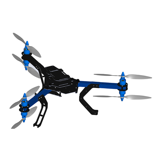
- Page 12 ESCs and wiring secured with zip ties FO L D I NG Your Y6 can fold for ease of transport. To collapse the blue arms, remove thumb nuts and bolts from outer holes, and slide blue arms toward black arm.
Need help?
Do you have a question about the Y6 and is the answer not in the manual?
Questions and answers