Advertisement
Quick Links
Advertisement

Related Manuals for 3DR 3DR ArduCopter Quad-C


Summary of Contents for 3DR 3DR ArduCopter Quad-C
- Page 1 3DR ArduCopter Quad-C...
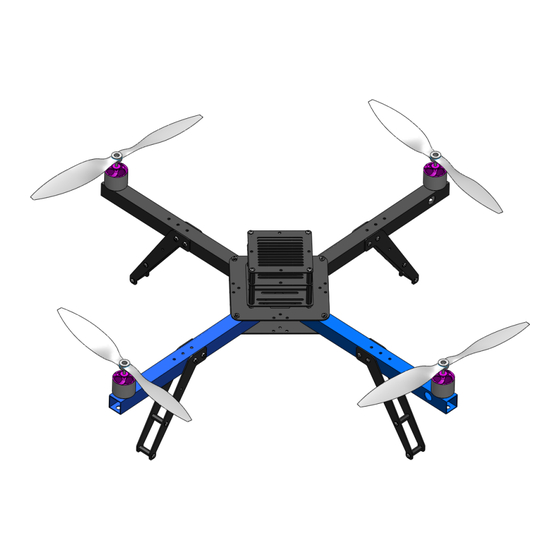
- Page 2 3DR ArduCopter Quad-C Thank you for purchasing a 3DR ArduCopter Quad kit. The 3DR ArduCopter Quad is a stable and supported multi-rotor frame in the ongoing development of the ArduCopter codebase on DIYDrones. It features a very durable Aluminum and G10 FR4 frame that can withstand hard impacts.
- Page 3 3DR ArduCopter Quad-C Hardware M3 Rubber Washer ............M3 Lock Washer ............M3 Nylon Nut ..............M3 Metal Nut ..............M3x5mm Plastic Screw ..........M3x5mm SS316 Screw ..........M3x25mm SS316 Screw ..........M2x30mm SS316 Screw ..........M3x08mm Spacer ............M3x18mm Spacer ............
-
Page 4: Assembly Guide
Assembly Guide Solder Motor and ESC Connectors Note: You may choose to solder the ESCs directly to the PDB. This will save time on this build and not require you to solder connectors to both the ESCs and the PDB. Soldering connectors however will allow you to easily remove components in the future. - Page 5 2. Slide a piece of shrink tubing over the bullet connectors and apply heat to shrink. heat can be applied with a soldering iron or a heat gun. Note: Female connectors should be fully covered by shrink tubing to avoid shorts. 3.
- Page 6 Choosing + or x Something to keep in mind during this build is which configuration your vehicle will be flown in. This is later chosen when setting up your APM in the Mission Planner. There is no effect on performance it is just a matter of personal preference. Both the + (Top) and X (Bottom) configurations are pictured above.
- Page 7 Arm Assembly x4 Note: If assembling a quad kit prior to Revision-C and installing 880kv (orange) motors the centered hole on the arm that allows room for the shaft to poke through needs to be drilled out to 10mm. 1. Attach the motor to the arm using two M3x5mm screws (Blue) and two M3 lock washers (Orange) making sure the screws go into the threaded holes in the motor and not the ventilation holes.
-
Page 9: Main Frame Assembly
Main Frame Assembly 1. Attach the bottom and top plates to one of the arm assemblies using an M3x30mm screw (Blue) and an M3x25mm screw (Green), secure with two M3 metal nuts (Pink). Note the four screws closer to the center of the vehicle are longer than those on the outside. This 4 longer screws will be used to hold the PDB cap and stack-up assembly. - Page 11 PDB Assembly 1. Solder the thin gauge red & black wire to “GND” and “5V OUT” on the bottom side of the PDB labeled “This Side Down”.
- Page 12 2. Solder the four wire connector to the motor signals starting with the green wire on the edge of the connector to M1 on the PDB. Work your way down the connector soldering the wires in order. Orange to M2, White to M3, and Yellow to M4. 3.
- Page 13 Wiring 1. Connect the three male bullets from the motors to the three bullet connectors on the ESCs. 2. Repeat for all 4 motors. 3. Place the PDB in the center hole of the vehicle as shown in the picture above. and fasten using four plastic M3 nuts.
- Page 14 5. Label the arms of the vehicle to correspond with the image above. Note: Keep in mind your chosen vehicle flying orientation. 6. Finally connect the 3 wire cables from the ESCs to their respective spots on the PDB signal pins. Remember ground is is the pin closest to the center of the board. Match the arm number (labeled in step 5) to the respective signal number (“S#”) on the PDB.
- Page 15 Mounting your APM APM can be mounted using double sided tape (3M Scotch Exterior Mounting Tape is recommended) or it can be bolted to the carrier plate. The series of slots on the carrier plate allow your APM to be bolted in both + and X configurations. Note: In + mode the front of the APM should face arm 3.
- Page 16 Assembling the stack-up 1. Place the APM carrier plate with the front of your APM pointing in between the blue arms (for X mode) onto the four M3x30mm screws sticking out of the top plate. 2. Secure the APM carrier plate with four M3x30mm nylon spacers.
- Page 17 3. Place a stack-up plate on top of the M3X30mm spacers and secure using four M3x18mm spacers. 4. Place a second stack-up plate on top of the M3x18mm spacers and secure using four M3x5mm nylon screws.
-
Page 18: Attaching Propellers
Attaching Propellers To attach the propellers use the collets included. Cut the plastic ring included with the propellers that fits snug around the threaded collet and insert it into the slot in the back of the propeller. Place the collet on the motor shaft and tighten to keep the propeller in place. - Page 19 We hope you enjoy your 3DR ArduCopter Quad. If you have any questions or concerns please feel free to contact us via email at : help@3drobotics.com For additional information on how to set up your 3DR ArduCopter Quad and more information on the ArduCopter codebase please visit the ArduCopter wiki at: http://code.google.com/p/arducopter...
Need help?
Do you have a question about the 3DR ArduCopter Quad-C and is the answer not in the manual?
Questions and answers