
Related Manuals for Technische Alternative UVR1611K-N-D


Summary of Contents for Technische Alternative UVR1611K-N-D
- Page 1 UVR1611K-N-D, UVR1611S-N-D Triac version A4.05 EN Freely programmable universal controller Operation Programming Installation instructions...
-
Page 3: Table Of Contents
Contents Safety requirements .............................. 4 Maintenance ............................... 4 Function mode ..............................4 Planning basics ..............................5 Basic standards ..............................6 Basic operation ..............................6 Display ................................6 Keys ................................6 Scroll-wheel ..............................7 Terms used ..............................7 User interface ................................. 8 MENU User .............................. -
Page 4: Safety Requirements
Safety requirements These instructions are intended exclusively for authorised contractors. All installation and wiring work on the controller must only be carried out in a zero volt state. The opening, connection and commissioning of the device may only be carried out by competent personnel. While doing so, they must observe all local safety requirements. -
Page 5: Planning Basics
Planning basics To ensure efficient programming, the following order has to be observed: The basic condition of writing the desired controller functions and its parameterizing is an accurate hydraulic diagram! This diagram must show what should be regulated and how. The sensor positions are to be defined according to the desired controller functions and drawn into the diagram. -
Page 6: Basic Standards
Basics Basic standards Basic operation Display The display consists of four information fields The top line constantly provides information about the actual output states. Blank field instead of number 5 = output five has not yet been parameterized Output five is active, runs in automatic mode and is temporarily switched off Output five is active, runs in automatic mode and is temporarily switched on Output five is active, runs in manual mode and is temporarily switched off Output five is active, runs in manual mode and is switched on at the moment... -
Page 7: Scroll-Wheel
Basics Scroll-wheel By means of the scroll-wheel, the selected menu can be gone through by the right pointer in the display. Small upward or downward showing arrows symbolize the possibility of further menu lines above or below the visible display range. If a parameter is to be changed, the pointer must be put in the desired position. -
Page 8: User Interface
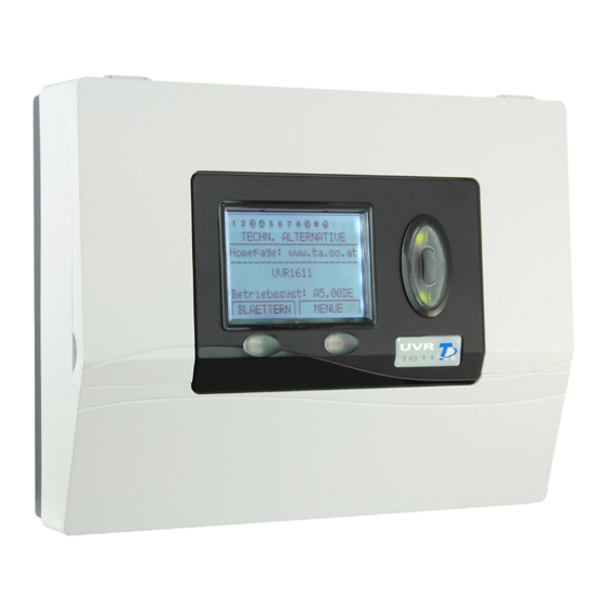
Main menu User interface After starting up, the display indicates this menu. TECHN. ALTERNATIVE ---------------------- Homepage: www.ta.co.at ---------------------- UVR1611 Operat. sys: Ax.xxEN Operating system: Version number of the software. The latest software (higher number) is available for download under http://www.ta.co.at. It can be transferred to the control unit by means of accessory equipment –... - Page 9 Main menu Version – shows only the same indication as after the starting up - i.e. the operating system of the unit. User – This menu permits the adjustment of the control level, the indication contrast and the back- ground lighting as well as the entrance into a so-called “User interface editor”, which allows the crea- tion of an own menu surface.
-
Page 10: Menu User
Menu User MENU User Here the following entries are listed: USER ---------------------- OPERATING MODE: User Technician Expert and by scrolling downwards: DISPLAY: Contrast: Brightness: Illumin. off after deactivated 00 sec. autom. changeover to func. overview:yes DATE / TIME: aut. changeover std/ summertime: yes Time since leaving the expert level:... - Page 11 Menu User DISPLAY: Brightness – The display has a background lighting, which is integrated in the circuit so that it does not need additional energy. The attenuation of the 12V relays to the 5V computer tension in many devices is transformed into heat, but in case of the UVR1611 also into light! Thus disconnect- ing does not save energy.
-
Page 12: Menu Date / Time
Menu Date / time Menu Measurement overview MENU Date / time Here the following entries are listed: DATE / TIME ---------------------- Thursday 16. 12. 2010 Std time: 00 : 00 All values can be selected and changed accordingly by means of the scroll-wheel. The date and time function has a power reverse of approximately three days in case of a blackout. -
Page 13: Menu Function Overview
Menu Function overview MENU Function overview All of the function modules offer a wide range of information, measurement values, and parameters that can be viewed via the menu "Functions." To give users a quick overview of the main settings, experts can use the "user interface editor" to display all of the information that users need to see from all the menus. -
Page 14: The User Interface Editor
Menu Function overview The user interface editor To keep the dialogue between users and the controller as simple as possible, an overview menu is automatically provided to present the most essential information that users need to know from the wide array of information available. The FUNCTION OVERVIEW serves that purpose in this device. Experts can use the "user interface editor"... - Page 15 Menu Function overview Programming example: The example in the function overview we will start with is the date, the time (both of which users can change), and the collector temperature. Enter the command S (source). Now, the display shows: User User is a special feature as it does not have anything to do with commands or entries and is the only source information that does not produce a heading.
-
Page 16: Tips And Tricks
Menu Function overview Tips and tricks The commands Delete < and Insert > acquire the inputs of the number of lines. The overview is all the more useful for users if the information is provided in a proper se- quence. -
Page 17: Menu Inputs
Menu Inputs MENU Inputs The menu "Inputs“ primarily serves as overview over the measured values of the inputs and/or sen- sors. Furthermore, it allows the expert the parameterizing of all used inputs if employed the following procedure: The line “Inputs” has already been selected and then pressed the scroll-wheel. Hereby the indication example is as follows: 1: T.collector The temperature of the collector is currently... - Page 18 Menu Inputs In the next step the name (designator) Buffer, bottom is to be assigned to the input 4. To do so, su- perset “designator groups” were specified such as General, Generator, Consumer, Line, Climate and others. General is a group which had to be taken over from old operating systems (< A1.21). Many names out of it are represented also in the other groups.
-
Page 19: Special Abilities Of The Inputs
Menu Inputs Special abilities of the inputs The inputs also permit as measured analogue variable Voltage including the necessary scaling. By this the determination of the value range is to be effected. For program reasons, the same configuration options are available with all inputs for the voltage measurement value. -
Page 20: Connection Of Electronic Sensors In Version Dl
Menu Inputs With “TYPE“ Pulse and “MEAS.VAR” Impulse there is also available a “DIVIDER” at the inputs 15 and 16. It indicates how many pulses have to arise at the input, so that a pulse is passed on to the functions. -
Page 21: Menu Outputs
Menu Outputs MENU Outputs The menu "Outputs“ primarily serves for the switching between the automatic and manual mode of the outputs. As in the status line of the outputs (top symbol line on the display) it is not possible to share information concerning the speed stages (if active), this indication was put down in the output menu. - Page 22 Menu Outputs After selecting the type (such as SPEED CTRL, since a solar pump shall run speed-controlled at output 1 later on) all available parameter lines are faded in. OUTPUT STATUS: TYPE: SPEED CTRL DESIGNATOR GROUP: General DES: ------- MODE: Wave packet (This line is suppressed in SWITCH OUTP) DELAY:...
-
Page 23: Particularities Of Output 14
Menu Outputs Particularities of output 14 Output 14 basically serves as a data link (DL-Bus9 but can also be used as a switch output for switch- ing an external relay and can be configured accordingly (unused / SWITCH.OUTP / DATA LINK). Output 14 as data link: Output 14 serves as a data link (DL bus) for the recording of measured values ("data logging") via C.M.I. -
Page 24: Particularities Of Outputs 15, 16
Menu Outputs Particularities of outputs 15, 16 Output 15, 16 = analogue outputs. These outputs provide a voltage between 0 and 10V for perfor- mance control of modern burners (burner modulation). They can be controlled by a PID function module, but also by other functions with an analogue value. The "scaling" offers the possibility of adapting the arithmetic value to the control range of the downstream device. -
Page 25: Anti-Blocking Protection
Menu Outputs Anti-Blocking Protection Circulating pumps, which do not run for longer periods (such as: heating circuit pump during the summer), often have starting problems as a result of inner corrosion. This problem can be easily avoided by activating the pump periodically for 30 seconds. The menu ANTI-BLOCKING PROT added after the output 16 permits to indicate the time and the outputs which are to receive this anti-skid control. -
Page 26: Menu Functions
Menu Functions MENU Functions The basic standards of the function menu In the menu “Functions“ all linkages concerning the control are to be set and parameterized (therein the control engineering of the entire solar and heating installation is described!). To this end, the unit has a set of function modules which can be registered successively and also several times in the list “Functions”. - Page 27 Menu Functions The following example shows how to set a new function. Indication example from the menu Functions: 5: CHARGING PUMP The function module already has been assigned to CHRG PUMP1 PAR? function 5 “Charging pump”. 6: NEW FUNCTION A new module can be entered. ----- PAR? ◄...
-
Page 28: Input Variables
Menu Functions Input variables Input variables serve as link to sensors and also to output variables from other function modules or definable parameters. The collector and the cylinder sensor are the typical input variable of the mod- ule SOLAR CONTROL. Another typical input variable for the module HEATING DEM. is the calculat- ed set temperature of the flow (T.flow SET) of the module HTG CIRC.CTRL. - Page 29 Menu Functions If another function module (also from the network) has been selected as a source, its first output variable (or first network input variable) in the following. An analogue value (temperature, computa- tion result) is not suitable for the enable control. An enable control only can be a switch, thus a digital value such as the output status of an already registered function module.
-
Page 30: Output Variables
Menu Functions Output variables They represent the result of a function module. They can be used directly for the switching of hard- ware output or serve as input variable for another module. If this output variable is to be used directly for the switching of a pump, the assignment can be made in the menu “OUTPUT VARIABLE”... - Page 31 Menu Functions A common pump with valves is often used in solar thermal systems with multiple consumers. There- fore, we assume the following: Double circuit solar thermal system with common pump and three-way valve Output 1 Common pump Output 3 Three-way valve In this example both the output 1 and the output 3 have to be activated in SOLAR 2 (1 and 3 dark- ened).
-
Page 32: Function Parameter
Menu Functions Function parameter Function parameters are set values which provide the user with the possibility to adapt the ready (i.e. with all preset function modules) control unit to the characteristics of his system. In the module SOLAR CONTROL these are parameters such as switch-on/off difference, maximum limit to the possible sensors. - Page 33 Menu Functions After entering the menu “TIME PRG:” all time programs are listed sequentially with their time win- dows. Indication example: Mo Tu We Th Fr Sa Su 05.00 - 07.00 12.00 - 22.00 00.00 - 00.00 Time window not used If the first time program applies to the period from Monday to Friday, these five symbols are darkened after each other.
-
Page 34: Function Status
Menu Functions Functions that have already been entered can be deleted at any time. It is recommended that a func- tion be deleted if function data are available from a similar project and the changes that have to be made are minor. To do so, you will find the command "DELETE FUNCTION" at the end of the menu in each function module. -
Page 35: Menu Messages
Menu Messages MENU Messages This module allows messages (error, malfunction, and others) to be triggered by specified events that last longer than 10 seconds. Any messages issued are automatically entered in the function over- view. In addition, output variables provide switching signals as long as the message is current. A total of eight message lines can be set up, each of which should be understood as an independent mod- ule. - Page 36 Menu Messages In the example below, a compare function as boiler thermostat shall issue the message "excess temperature" to set off an acoustic warning signal when excess temperature is in the boiler (=event), switch on dominantly the heating circuit pump and the cylinder charging pump and switch off the burner demand: INPUT VARIABLE: OUTPUT VARIABLE:...
-
Page 37: Menu Network
Menu Network MENU Network This menu contains all of the information and settings needed to set up a CANopen network. Entire menu view: Node No.: The device has network address 1 ENABLE: Participation in bus communication admissible Autooperat.: Device communicates with other bus participants without master Status: operat and is active... -
Page 38: Output Variable
Menu Network Output variable A total of 16 digital and 16 analogue network outputs can be programmed. All of the input and output statuses, output variables for the functions, network status, sensor status, and the status of messages can be used. DIGITAL NETW. -
Page 39: Input Variable
Menu Network Input variable A total of 16 digital and 16 analogue network inputs can be programmed. They are indicated by the transmission node number and the number of the network output variable of the transmission node. INPUT 1: NW Node: analg.NW.outp.: Source: Value:... -
Page 40: Data Logging
Menu Network Data logging There are 2 data logging possibilities: Via the data link (DL-bus): When data logging via the DL-bus, there is a constant data flow from the controller to the C.M.I. or the data converter D-LOGG. The values or states of all inputs, switch outputs and the values of up to two heat meters are specified as a data record. - Page 41 Menu Network Speed stages of the outputs: If the speed stages of an output are also to be captured, the digital value must have the same number as the corresponding output, e.g., output 6 must have been allocated digital value 6. If the output is allocated to another digital value, then status output still occurs (ON/OFF), but no speed stage output.
-
Page 42: Network Nodes
Rev.Nr.: Node product description Des.: These data are fixed values specified by Technische Alternative GmbH and cannot be changed. MENU Load menu page: This is used to access the menu level of the selected network node. The controller now serves as a display for Version this device. -
Page 43: Menu Data Administration
Menu Data administration MENU Data administration In this menu the commands concerning the administration and protection of the function data as well as the update of the operating system are listed. The menu items for data transfer are valid only for Bootloader BL-NET. -
Page 44: Data Exchange With The Pc And/Or Bootloader
Menu Data administration Create backup copy – The function data can be saved in a backup copy. By this, it is possible to change the program or the parameters without losing the existing function data. If a backup copy has been created, than appears as a further menu option: Load backup copy –... - Page 45 Menu Data administration DATA <=> BOOTLOADER: Download data – By means of the Bootloader the protected function data in the PC are transmitted into the control unit via the CAN Bus or the infrared interface and thus the current programming is overwritten.
-
Page 46: Installation Instructions
Installation instructions Installation instructions Sensor installation The sensors must be arranged and installed properly for the system to function correctly. To this end, make sure also that they are completely inserted in the immersion sleeves. The threaded cable con- nections provided serve as a strain relief. The clip-on sensors must be insulated to protect them from being influenced by the ambient temperature. -
Page 47: Sensor Lines
Installation instructions DHW sensor: When the control system is used in DHW systems with an external heat exchanger and speed-controlled pump, changes in the amount of water have to be reacted to quickly. Hence, the DHW sensor has to be put directly on the heat exchanger’s outlet. A T-shaped connector should be used to insert the ultrafast sensor (special accessory) in the outlet using an O-ring. -
Page 48: Installing The Device
Installation instructions Installing the device The controller can be used as a surface mounted device or as an integrated device: Surface mounted controller with mounting base UVR 1611K-N Fix the mounting base to the wall at eye level height (approximately 1.6 m) using the fixing materials supplied. - Page 49 Installation instructions Opening the mounting base CAUTION Always disconnect the mains plug before opening the mounting base. Open the top flap. View with open cover With two large screwdrivers, push both locking clamps (arrows in the diagram on the left) and lever the device out of the mounting base.
-
Page 50: Dimensioned Drawings
Installation instructions Dimensioned drawings External dimensions, mounting base... - Page 51 Installation instructions Dimensions, mounting base fixings Dimensions, terminal mounting plate Unlocking clamps for support rail mounting (top-hat rail TS35)
- Page 52 Installation instructions Dimensions, controller with terminal mounting plate (=UVR1611S-N) Cut-out dimensions for controller UVR1611S-N: 138 x 91 mm, installed depth including termi- nal mounting plate: 70 mm...
-
Page 53: Can Bus Network
Electrical connection CAN BUS network Guidelines for the topology of a CAN network Technical principles The CAN BUS comprises the cables CAN-High, CAN-Low, GND and one +12 V supply cable for BUS components without their own power supply. The combined total load of all devices with 12 V and 24 V supply must not exceed 6 W. -
Page 54: Lighting Protection
In order to protect the individual components of a CAN network against indirect lightning strike, we recommend the use of surge arresters specifically developed for BUS systems. Examples: CAN bus surge arresters CAN-UES from Technische Alternative Gas discharge arrester for indirect earthing EPCOS N81-A90X... - Page 55 Electrical connection Network (across several buildings) without CAN bus converter CAN-BC/C: Option- Option- Indirect earthing Optional Indirect earthing Max. cable length: 1000 m at 50 kbit/s The screen must be continued at every network node and earthed at a single point, as close to the cable centre as possible.
-
Page 56: Cable Selection And Network Topology
Electrical connection Cable selection and network topology Screened twisted pairs have proven useful in CANopen networks. These are cables with twisted pairs of conductors and a shared external screen. Such cables are relatively resistant to EMC inter- ference and can still carry 50 kbit/s for up to 1000 m. The CANopen recommendations (CiA DR 303- 1) for cable cross-sections are given in the table below. - Page 57 Electrical connection Example: Connection of three network nodes (NK) with a 2x2-pole cable and termination of the terminal network nodes (network inside one building) Each CAN network is to be provided with a 120 ohm BUS terminator at the first and last network subscriber (= termination).
-
Page 58: Data Link (Dl Bus)
Changing to cable types with different characteristic impedances is only permitted via signal separa- tion through a CAN bus converter. However, such networks do not comply with the recommended specification. Technische Alternative RT GmbH therefore cannot guarantee trouble-free operation if one of the three options listed above is applied. -
Page 59: Termination Guide
Electrical connection Termination guide Each controller is supplied with a guide containing the terminal markings, which is clamped between the low voltage and 230 V terminals. After completion of the electrical connection, this guide can either be retained inside the controller or removed. View with the guide fitted:... -
Page 60: Complete Overview Of Terminals
Electrical connection Complete overview of terminals CAUTION This connection cable requires further Sensor earth fittings. Switching outputs Phase conductor L..Neutral conductor N..PE..Earth conductor Root C..Triac output NO..N/O contact NC..N/C contact Relay output, normally open contact (N/O) Relay output, normally open + normally closed contact (N/O + N/C) Caution: Output A5 is potential-free, i.e. -
Page 61: Connection Auxiliary Relay Hirel-230V
Electrical connection Connection auxiliary relay HIREL-230V Example: Connection HIREL-230V for outputs 12 and 13 Program outputs A12 and A13 as switching outputs Sensor earth Fuse 6,3A fast HIREL-230V Mains The mains connection (L, N) is looped to the control- 230V 50Hz ler via the relay module terminals.. -
Page 62: Connection Auxiliary Relay Hirel-Pf
Electrical connection Connection auxiliary relay HIREL-PF Example: Connection HIREL -PF for outputs 12 und 13 Program outputs A12 and A13 as switching outputs Drilled hole Relay 2 HIREL-PF Relay 1 This connection enables the HIREL-PF relay contacts to switch the phase conductor (230 V) to become conductive. -
Page 63: Technical Data Uvr1611 (Triac Version)
Power draw Max. 4.2 W (without accessory equipment) Protection IP40 Permissible ambient +5 to +45°C temperature Standard delivery UVR1611K-N-D: The UVR1611, console including all terminals, while attachment material, strain reliefs, operating instructions UVR1611S-N-D: Device with terminal mounting plate, operating instructions... -
Page 64: Tips On Troubleshooting
Tips on troubleshooting If there is no display, there has been a power outage. First check the fuse (6.3A, quick-blow) that protects the device and the outputs (pumps, valves, etc.) from short circuits and the outputs in con- nection with the integrated overvoltage protection. The glass tube fuse is located on the rear side of the controller behind a screw cap. - Page 65 Not possible to manually switch an output: If the output has speed control (A1, A2, A6 or A7) and is actually set to speed control, pay at- tention to the speed stage when using manual mode. Set to stage 30 when testing the pump's basic function.
-
Page 66: Troubleshooting In The Can Network
Troubleshooting in the CAN network To localize the error, switching off of a part of the network at a time in order to see when the error disappears is recommended. General tests: Node numbers - no node number may be allocated twice ... - Page 67 Technische Alternative RT GmbH Address: A- 3872 Amaliendorf, Langestraße 124 This declaration of conformity is issued under the sole responsibility of the manufacturer. Product name: UVR1611K, UVR1611K-N-D, UVR1611K-N, UVR1611S, UVR1611S-N, UVR1611S-N-D, UVR1611E-NM, UVR1611E-DE, UVR1611E-NP Product brand: Technische Alternative RT GmbH Product description:...
- Page 68 Note: The following guarantee conditions do not in any way limit the legal right to a guarantee, rather expand your rights as a consumer. 1. The company Technische Alternative RT GmbH provides a two-year guarantee from the date of purchase by the end consumer for all the devices and parts which it sells. Defects must be reported immediately upon detection and within the guarantee period.
Need help?
Do you have a question about the UVR1611K-N-D and is the answer not in the manual?
Questions and answers