Miller LMSW-52 Owner's Manual
Portable resistance spotwelders
Hide thumbs
Also See for LMSW-52:
- Owner's manual (32 pages) ,
- Technical manual (32 pages) ,
- Owner's manual (28 pages)

Related Manuals for Miller LMSW-52


Summary of Contents for Miller LMSW-52
- Page 1 OM-716 199 981A January 2001 Processes Resistance Spot Welding Description MSW-41, MSW-41T, MSW-42, MSW-42T, And LMSW-52, LMSW-52T Portable Resistance Spotwelders Visit our website at www.MillerWelds.com...
- Page 2 They had to be the best you could buy. Today, the people that build and sell Miller products continue the tradition. They’re just as committed to providing equipment and service that meets the high standards of quality and value established in 1929.
-
Page 3: Table Of Contents
TABLE OF CONTENTS SECTION 1 – SAFETY PRECAUTIONS ..........1-1. -
Page 5: Section 1 - Safety Precautions
SECTION 1 – SAFETY PRECAUTIONS - READ BEFORE USING spotom _nd_11/99 1-1. Symbol Usage Means Warning! Watch Out! There are possible hazards with this procedure! The possible hazards are shown in the adjoining symbols. Y Marks a special safety message. This group of symbols means Warning! Watch Out! possible ELECTRIC SHOCK, MOVING PARTS, and HOT PARTS hazards. -
Page 6: Additional Symbols For Installation, Operation, And Maintenance
MOVING PARTS can cause injury. FUMES can be hazardous. Coatings, cleaners, paints, and platings can pro- The tong tips, tongs, and linkages move during duce fumes when welded. Breathing these fumes operation. can be hazardous to your health. Keep away from moving parts. Do not breathe the fumes. -
Page 7: Section 1 - Consignes De Sécurité - Lire Avant Utilisation
SECTION 1 – CONSIGNES DE SÉCURITÉ – LIRE AVANT UTILISATION spotom _nd_Fre_4/97 1-1. Signification des symboles Signifie Mise en garde ! Soyez vigilant ! Cette procédure présente des risques de danger ! Ceux-ci sont identifiés par des symboles adjacents aux directives. Y Identifie un message de sécurité... -
Page 8: Dangers Supplémentaires En Relation Avec L'installation, Le Fonctionnement Et La Maintenance
DES ORGANES MOBILES peuvent LES FUMÉES peuvent être provoquer des blessures. dangereuses. Pendant le soudage, les bras et électrodes se Lors du soudage, les revêtements, produits de net- déplacent. toyage, peintures et placages peuvent dégager des fumées. Leur inhalation peut être dangereuse. Ne pas s’approcher des organes mobiles. -
Page 9: Section 2 - Introduction
(19.1 kg) (20.4 kg) *Based on 10 second time period; means unit can weld for 5 seconds out of each 10 second time period. Model MSW-41, 41T MSW-42, 42T LMSW-52, 52T 6 in 12 in 18 in 6 in 12 in... - Page 10 B. Dressing The Tips New Tip Used Tip Requiring Dressing Dressing Method – Keep top diameter same as a new tip. d = <1/8 in (3.2 mm) diameter for 1.5 kVA models; 5/32 in (4 mm) for 2.5 kVA models Tools Needed: OM-716 Page 6...
-
Page 11: Installing Or Cleaning Tongs
3-2. Installing Or Cleaning Tongs Y Turn off and unplug welder. Y OSHA and/or local codes may require addi- Be sure tong ends are clean tional guarding to suit the application. corroded before installing. Clean tongs with fine steel wool. Bottom Tong: Bottom Tong Hole In Spatter Guard... -
Page 12: Adjusting Tong And Hand Lever Pressure
3-3. Adjusting Tong And Hand Lever Pressure Tools Needed: 9/16, 11/16 in Ref. ST-800 156 Y Turn off and unplug welder. splash out around the nugget area. To decrease tong pressure, loosen the rear If tong pressure is too weak, parts are nut and turn the front nut up to the pivot cast- Y Excessive tong pressure can dam- loose when the tongs close, severe arc-... -
Page 13: Installing Handle
3-4. Installing Handle MSW 41 And 41T Models MSW 42, 52, 42T, And 52T Models Tools Needed: Ref. ST-802 056 7/16, 3/8 in Y Turn off and unplug welder. Install handle onto the spot welder as shown above. For 42, 52, 42T, and 52T Models, Wodden Handle install handle onto either side as desired for Handle Bolt... -
Page 14: Mounting Control Box
3-5. Mounting Control Box Push-in slots are provided on rear of box for wall mounting if desired. The slots will fit over 1/4 inch hex- head screws. To mount box, pro- ceed as follows: Control Box Push-In Slots (Not Shown) Use slots as template and install screws at desired locations leaving 1/8 inch stickout. -
Page 15: Connecting Input Power (Non-T Models)
3-7. Connecting Input Power (Non-T Models) Y Input power supply wiring and receptacle must meet National Electrical Code and all other code requirements. Operate spot welder from a sepa- rately fused or circuit breaker pro- tected circuit, and use correct size input conductors. -
Page 16: Section 4 - Operation
SECTION 4 – OPERATION 4-1. Controls (T Models) Spot Weld Timer And Pilot Light Weld time adjusts from 0 to 5 seconds. The pilot light turns on when the weld cycle begins and off when the cycle ends. Hand Lever Use lever to open and close tongs. -
Page 17: Section 5 - Maintenance And Troubleshooting
SECTION 5 – MAINTENANCE AND TROUBLESHOOTING 5-1. Routine Maintenance Y Disconnect power before maintaining. Every Use 3 Months 6 Months Blow Off Vacuum Replace Inspect Unit Unreadable Tips Labels During Heavy Service, Clean Monthly 5-2. Overload Protection For 220 Volts Model Y Turn Off unit and disconnect input power. - Page 18 Trouble Remedy Clean ends of tongs and tong holders (see Section 3-2). Check power switch (T models only) and/or start switch. Replace if necessary. Longer than normal weld time required. Dress or replace tips (see Section 3-1). Clean workpieces. Adjust tong pressure (see Section 3-3). Clean ends of tongs and tong holders (see Section 3-2).
-
Page 19: Section 6 - Electrical Diagrams
SECTION 6 – ELECTRICAL DIAGRAMS SA-162 466-B Figure 6-1. Circuit Diagram For 110 Volts T-Models SA-072 065-B Figure 6-2. Circuit Diagram For 220 Volts T-Model OM-716 Page 15... - Page 20 SA-162 467-B Figure 6-3. Circuit Diagram For 110 And 220 Volts Non-T Models OM-716 Page 16...
- Page 21 Notes OM-716 Page 17...
-
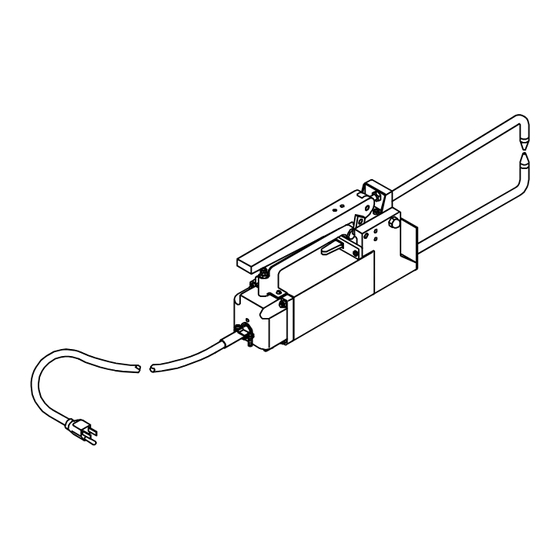
Page 22: Section 7 - Parts List
SECTION 7 – PARTS LIST Hardware is common and not available unless listed. 38–Fig 6–2 ST-145 048-C Figure 7-1. Main Assembly OM-716 Page 18... - Page 23 Quantity Model Item Dia. Part Mkgs. Description 41,41T 42,42T 52,52T Figure 7-1. Main Assembly ....019 643 HANDLE, carrying ........
- Page 24 Replace Coils At Factory Or Factory Authorized Service Station. Quantity Model Item Part Description 41,41T 42,42T 52,52T Figure 7-2. Transformer, Power Main (Fig 7-1 Item 38) 095 345 095 350 095 354 ..026 601 INSULATION .
- Page 25 Quantity Model Item Dia. Part Mkgs. Description 115V 230V Figure 7-3. Timer, Spot (230V Illustrated) 041 081 041 082 ......NAMEPLATE, (order by model and style numbers) .
-
Page 26: Chart 7-1. Spot Welder Tips
Chart 7-1. Spot Welder Tips 6” (152 mm) 040 197 3-1/2” (89 mm) Standard Flat 12” (305 mm) 040 198 18” (457 mm) 040 199 STANDARD 040 211 040 212 6” (152 mm) 040 200 3-1/2” (89 mm) Offset 12” (305 mm) 040 201 18”... - Page 27 Effective January 1, 2000 (Equipment with a serial number preface of “LA” or newer) This limited warranty supersedes all previous Miller warranties and is exclusive with no other Warranty Questions? guarantees or warranties expressed or implied. Call LIMITED WARRANTY – Subject to the terms and conditions APT, ZIPCUT &...
- Page 28 Distributor Address City State For Service Call 1-800-4-A-Miller or see our website at www.MillerWelds.com to locate a DISTRIBUTOR or SERVICE AGENCY near you. Always provide Model Name and Serial/Style Number. Contact your Distributor for: Welding Supplies and Consumables Options and Accessories...
Need help?
Do you have a question about the LMSW-52 and is the answer not in the manual?
Questions and answers