
Related Manuals for Miller LBP-350


Summary of Contents for Miller LBP-350
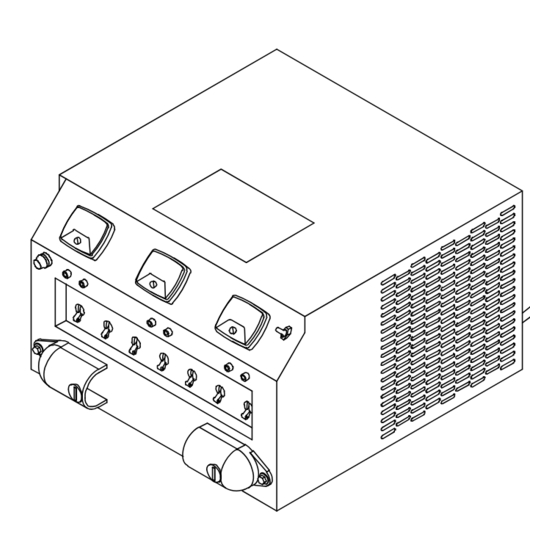
- Page 1 OM-2807 191256G 2021-09 Description Portable Load Bank To Load Test AC Or DC Welding Power Sources LBP-350 For product information, Owner’s Manual translations, and more, visit www.MillerWelds.com...
- Page 2 We know you don’t have time to do it any other way. That’s why when Niels Miller first started building arc welders in 1929, he made sure his products offered long-lasting value and superior quality.
-
Page 3: Table Of Contents
TABLE OF CONTENTS SECTION 1 − SAFETY PRECAUTIONS - READ BEFORE USING ........1-1. -
Page 5: Section 1 − Safety Precautions - Read Before Using
SECTION 1 − SAFETY PRECAUTIONS - READ BEFORE USING som 2020−02 Protect yourself and others from injury — read, follow, and save these important safety precautions and operating instructions. 1-1. Symbol Usage DANGER! − Indicates a hazardous situation which, if Indicates special instructions. - Page 6 D Do not cut or weld on tire rims or wheels. Tires can explode if heat- FUMES AND GASES can be hazardous. ed. Repaired rims and wheels can fail. See OSHA 29 CFR 1910.177 listed in Safety Standards. D Do not weld on containers that have held combustibles, or on Welding produces fumes and gases.
-
Page 7: Additional Hazards For Installation, Operation, And Maintenance
D Never weld on a pressurized cylinder − explosion will result. CYLINDERS can explode if damaged. D Use only correct compressed gas cylinders, regulators, hoses, and fittings designed for the specific application; maintain them Compressed gas cylinders contain gas under high and associated parts in good condition. -
Page 8: California Proposition 65 Warnings
H.F. RADIATION can cause interference. ARC WELDING can cause interference. D High-frequency (H.F.) can interfere with radio D Electromagnetic energy can interfere with navigation, safety services, computers, and sensitive electronic equipment such as communications equipment. computers and computer-driven equipment such as robots. D Have only qualified persons familiar with electronic equipment D Be sure all equipment in the welding area is electromagnetically perform this installation. -
Page 9: Section 2 − Consignes De Sécurité − Lire Avant Utilisation
SECTION 2 − CONSIGNES DE SÉCURITÉ − LIRE AVANT UTILISATION som_2020−02_fre Pour écarter les risques de blessure pour vous−même et pour autrui — lire, appliquer et ranger en lieu sûr ces consignes relatives aux précautions de sécurité et au mode opératoire. 2-1. - Page 10 D Déplacer toutes les substances inflammables à une distance de LES PIÈCES CHAUDES peuvent 10,7 m de l’arc de soudage. En cas d’impossibilité les recouvrir provoquer des brûlures. soigneusement avec des protections homologués. D Ne pas toucher à mains nues les parties chaudes. D Ne pas souder dans un endroit là...
-
Page 11: Symboles De Dangers Supplémentaires En Relation Avec L'installation, Le Fonctionnement Et La Maintenance
D Protéger les bouteilles de gaz comprimé d’une chaleur excessive, Les CHAMPS ÉLECTROMAGNÉTIQUES (CEM) des chocs mécaniques, des dommages physiques, du laitier, des peuvent affecter les implants médicaux. flammes ouvertes, des étincelles et des arcs. D Placer les bouteilles debout en les fixant dans un support station- D Les porteurs de stimulateurs cardiaques et naire ou dans un porte-bouteilles pour les empêcher de tomber ou autres implants médicaux doivent rester à... -
Page 12: Proposition Californienne 65 Avertissements
D Effectuer régulièrement le contrôle et l’entretien de l’installation. LIRE LES INSTRUCTIONS. D Maintenir soigneusement fermés les portes et les panneaux des sources de haute fréquence, maintenir les éclateurs à une distan- D Lire et appliquer les instructions sur les ce correcte et utiliser une terre et un blindage pour réduire les étiquettes et le Mode d’emploi avant l’instal- interférences éventuelles. -
Page 13: Section 3 − Specifcations
SECTION 3 − SPECIFCATIONS 3-1. Specifications Specification Description Type Of Input Power Single-Phase 115 Volts AC, 0.6 Amperes, 50/60 Hertz Input Power Cord With Plug 13 ft (3.9m) long Connection Terminals 1/2 in. (12.7 mm) Overall Dimensions Including Handle Length: 19.25 in. (489 mm); Width: 20.625 in. (524 mm); Height: 11.25 in. (286 mm) and Connection Terminal Covers Weight Net: 46 lb (20.9kg) -
Page 14: Section 4 − Installation
SECTION 4 − INSTALLATION 4-1. Selecting A Location And Moving Portable Load Bank * Add 3 in. (76 mm) For Handle On Left Side 17-5/8 in. Dimensions And Weight (448 mm)* 46 lb (20.9 kg) 11-1/4 in. (286 mm) ** Add 1-3/4 in. (45 mm) 17-1/2 in. -
Page 15: Cable Connections To Welding Equipment
4-2. Cable Connections To Welding Equipment Turn Off welding power source or stop engine on welding generator before Connections To Welding Power Source making any connections. Welding Power Source Or Welding Generator Customer-supplied 1/0 AWG Cables−−Use Shortest Cables As Possible Portable Load Bank Terminal Lugs Install terminal lugs of proper am-... -
Page 16: Section 5 − Operation
SECTION 5 − OPERATION 5-1. Front Panel Controls Analog AC/DC Voltmeter AC Load Amperage Jack Plugs der load, but there must be at least 1 switch On for every 50 Amps of applied load. The An external AC Ammeter can be plugged in This meter displays the voltage present at switches are all identically rated at 50 Amps;... -
Page 17: Rated Output Testing Procedure
5-2. Rated Output Testing Procedure This procedure requires that the load bank and welding power source/welding generator electrical power be ON. For this procedure, the load bank is used to determine if a welding power source or welding generator is supplying rated output. Rated output usually indicates the welding power source or welding generator is working correctly. -
Page 18: Replacing Fuse F1
6-2. Replacing Fuse F1 Turn welding power source or stop engine on weld- ing generator and disconnect load bank input power plug from receptacle. See Parts List for size and rating of fuse. Fuse F1 Fuse F1 protects the Load Voltage Jack Plugs from overload conditions. - Page 19 6-3. Troubleshooting Table Trouble Remedy Unit is completely inoperative; fan does Be sure input power cord is plugged in and that receptacle is receiving input power. not run. Unit is completely inoperative; fan Thermostat TP1 open caused by overheating. Allow cooling period for TP1 to close and remove overload condition.
-
Page 20: Section 7 − Electrical Diagram
SECTION 7 − ELECTRICAL DIAGRAM 186746-C Figure 7-1. Circuit Diagram OM-2807 Page 16... -
Page 21: Section 8 − Parts List
188052 Label, Miller 5.375 x 6.250 ........ - Page 22 Item Dia. Part Mkgs. Description Quantity Figure 8-2. Inside View, Fan Motor End ..... 183539 Base ............
- Page 23 Item Dia. Part Mkgs. Description Quantity Figure 8-3. Inside Of Front Panel ....118681 Switch, Tgl DPDT 15A 125VAC On−None−(On) ....
- Page 24 Item Dia. Part Mkgs. Description Quantity Figure 8-4. Resistor Tunnel, Rear View ..... 059726 Insulator, End ..........
- Page 25 Item Dia. Part Mkgs. Description Quantity Figure 8-5. Resistor Tunnel, Front View ....261372 Thermostat, NC Open 160F Close 140F ......
- Page 26 Notes Welding Tip: Securely connect work clamp to a clean area close to the weld joint. OM-2807 Page 22...
- Page 27 Effective January 1, 2021 (Equipment with a serial number preface of NB or newer) This limited warranty supersedes all previous Miller warranties and is exclusive with no other guarantees or warranties expressed or implied. LIMITED WARRANTY − Subject to the terms and conditions TIG Torches (No Labor) below, Miller Electric Mfg.
- Page 28 Contact the Delivering Carrier to: File a claim for loss or damage during shipment. For assistance in filing or settling claims, contact your distributor and/or equipment manufacturer’s Transportation Department. © ORIGINAL INSTRUCTIONS − PRINTED IN USA 2021 Miller Electric Mfg. LLC 2021−01...
Need help?
Do you have a question about the LBP-350 and is the answer not in the manual?
Questions and answers