
Subscribe to Our Youtube Channel
Related Manuals for Contec ADI12-8(USB)GY


Summary of Contents for Contec ADI12-8(USB)GY
- Page 1 PC-HELPER Isolated Analog Input Module for USB ADI12-8(USB)GY User’s Guide CONTEC CO., LTD.
-
Page 2: Trademarks
No part of this document may be copied or reproduced in any form by any means without prior written consent of CONTEC CO., LTD. CONTEC CO., LTD. makes no commitment to update or keep current the information contained in this document. -
Page 3: Product Configuration
*1 The CD-ROM contains the driver software and User’s Guide (this guide) Check the contents to make sure that you have everything listed below. If you do not have all the items or have any damage, contact your distributor or CONTEC group office where you purchased. -
Page 4: Table Of Contents
Software Installation ............. 12 Illustration of Menu Screen ........12 Installation of API-USBP(WDM) Development Environment ............... 13 Installing the Utility ..........14 Connecting to a PC ............15 Setting Properties Using Device Manager ....17 Connecting to an External Device ......... 19 ADI12-8(USB)GY... - Page 5 Setting a Device ID ............48 Connection between Modules ........49 Stack Connection Locking Devices ......49 How the Stack Connection Locking Device Works .. 50 Connecting the Module ..........51 Removing the Module ..........52 Product Specification ..........53 ADI12-8(USB)GY...
- Page 6 Hardware Specification..........53 Software Specification............ 55 Circuit Block Diagram ........... 56 Timing Chart ..............57 Physical Dimensions ............58 Appendix..............61 Glossary ................61 ADI12-8(USB)GY...
- Page 7 ADI12-8(USB)GY...
-
Page 8: Introduction
Sampling can be started and stopped by software and level comparison (compares the level of a specified channel with a specified compare level value) triggers. The sampling period can be controlled by the internal clock (high-precision timer included on the board). ADI12-8(USB)GY... - Page 9 This product is equipped with an attachment for mounting on 35-mm DIN rails on the back, allowing this product to be attached onto and detached from DIN rails. LabVIEW is supported by a plug-in of dedicated library. Using the dedicated library makes it possible to create each application for LabVIEW. ADI12-8(USB)GY...
-
Page 10: Support Software
: POW-AD22GY DC-DC power supply unit (input: 10 - 30VDC, output: 5VDC 3.0A) : POW-DD10GY DC-DC power supply unit (input: 30 - 50VDC, output: 5VDC 3.0A) : POW-DD43GY * Check the CONTEC’s Web site for more information on these options. ADI12-8(USB)GY... -
Page 11: Customer Support
You can download updated driver software and differential files as well as sample programs available in several languages. Note! For product information Contact your retailer if you have any technical question about a CONTEC product or need its price, delivery time, or estimate information. Limited One-Year Warranty CONTEC product is warranted by CONTEC Co., LTD. -
Page 12: How To Obtain Service
Please obtain a Return Merchandise Authorization number (RMA) from the CONTEC group office where you purchased before returning any product. * No product will be accepted by CONTEC group without the RMA number. Liability The obligation of the warrantor is solely to repair or replace the product. In no event... -
Page 13: Handling Precautions
Even if you use the product again, please be sure to read the manual to confirm the content. - Please do not modify the product. CONTEC will bear no responsibility for any problems, etc., resulting from modifying the product. ADI12-8(USB)GY... - Page 14 CONTEC will disclaim any responsibility for products whose casing has been opened. - Regardless of the foregoing statement, CONTEC assumes no responsibility for any errors that may appear in this document nor for results obtained by the user as a result of using this product.
-
Page 15: Environment
Store the module into a box with wrapper. Please store the module in normal temperature avoiding direct sunlight, shock and vibration, magnetic field and static electricity. Disposal When disposing of the product, follow the disposal procedures stipulated under the relevant laws and municipal ordinances. ADI12-8(USB)GY... -
Page 16: Module Nomenclature
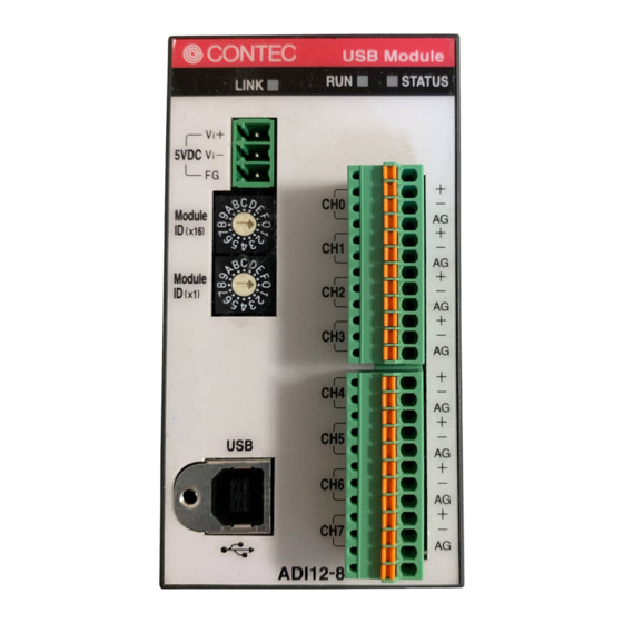
USB Port *1 Figure 2.1. Nomenclature of Module Components < ADI12-8(USB)GY > *1 When you use the module in a noisy environment or are nervous about noise, ground the module (using a M3 screw). *2 When you use the module in a noisy environment or are nervous about noise, connect the FG pin in the +5 VDC input terminal to the ground. - Page 17 2. Module Nomenclature ADI12-8(USB)GY...
-
Page 18: Setup
There are two rotary switches, moreover, “x16” and “x1” represent high bits and low bits of Module ID respectively. Module Module ID(x16) ID(x16) Module Module ID (x1) ID (x1) Module ID 00h Module ID 12h [Factory Settings] [Factory Settings] Figure 3.2 Setting a Module ID ADI12-8(USB)GY... -
Page 19: Setup Flow
- Please set up the supplied CD-ROM if it has not been set up. The menu starts automatically. - If the menu do not start, launch X:AUTORUN.EXE(X:CD-ROM drive) from [Run…] in Start menu. - The screen design may be different. ADI12-8(USB)GY... -
Page 20: Installation Of Api-Usbp(Wdm) Development Environment
Step1 Clicking on “Install Development or Execution Environment” [API-USBP(WDM) Installer] dialog box displays. Step2 Selecting “Advanced Analog I/O driver” Step3 Clicking on “Install” Button Please perform installation following the directions on the screen. And thus the installation is completed. *The screen design may be different. ADI12-8(USB)GY... -
Page 21: Installing The Utility
The utility is application with which you can verify device operation easily. Run the “X:\ USBP_UTILITY\ ENG\ DioMnt\ setup.exe (X:CD-ROM drive)” from the [Run] of start menu. Follow the instructions that appear on the screen. This completes the installation. ADI12-8(USB)GY... -
Page 22: Connecting To A Pc
It may cause a trouble in recognizing and operating the device according to the kind of USB hub. If you use the USB hub, we encourage you to take advantage of the CONTEC’s product loan service to confirm operation before purchasing. Step1 Setting supplied CD-ROM “API-USBP(WDM)”... - Page 23 Point Please specify the path for supplied CD as follows in the case of failure in detecting automatically. X:\INF\WDM\AIO (X: CD-ROM drive) Step4 Clicking on [Finish] button Click on [Finish] button to complete the installation of USB driver. ADI12-8(USB)GY...
-
Page 24: Setting Properties Using Device Manager
Step1 Starting Device Manager Right-click on [My Computer] and select [Properties] to start device manager. * [XXXXX] within CONTEC Devices expresses the name from getting rid of GY from the model of USB module. In the case of Windows XP/2000 From [Start] menu, click on [Settings]-[Control Panel]-[System] and then click on [Device Manager] button in [Hardware] tab. - Page 25 - Please use the device name specified in last step for initialization function when initialization is performed using API function. When running on other PC, it can run without changing the application for the same device name being specified. ADI12-8(USB)GY...
-
Page 26: Connecting To An External Device
Analog ground Figure 3.3. Signal Layout on the Interface Connector < ADI12-8(USB)GY > Connection Method When connecting the Module to an external device, you can use the supplied connector plug. When wiring the Module, strip off approximately 7 - 8 mm of the covering for the cable, and insert the bare wire by pressing the orange button on the connector plug. - Page 27 CH1 [+] Signal source (1) CH1 [-] Point B Potential difference between grounds: 0.2V ADI12-8(USB)GY Signal source (2) ’s ground Figure 3.5. Connecting an Interface Connector and Connectors That Can Be Used As shown in Figure 3.5, when several signal sources are measured, the potential differences between the module’s ground and signal source’s ground may be...
- Page 28 - If either the [+] or [-] input pin is not connected, the resulting conversion data can be unpredictable. If a channel is not connected to a signal source, both its [+] input and [-] input pins must be connected to the analog ground. ADI12-8(USB)GY...
- Page 29 Furthermore, when several current sources are measured, the potential difference between their GNDs must not exist. For ADI12-8(USB)GY, the CPU in the module is isolated from external device whereas the analog input channels is not isolated each other, therefore, the analog grounds cannot be connected together.
-
Page 30: Sampling
Sampling Input Range and Conversion Data On ADI12-8(USB)GY, the range of input can be selected from 0 - 5V, 0 - 10V, ±5V and ±10V by using software. The analog signals are converted into digital signals with a 12-bit resolution based on the range setting. -
Page 31: Sampling Rate
Sampling Rate A/D Conversion Timing The conversion time of Analog-Digital converter in ADI12-8(USB)GY is 10µsec, and total time indicates 'number of channels x 10 µsec + 20µsec' until converting from each analog signals to digital data. The time difference between 0 channel and 1 channel or later is 10µsec... -
Page 32: Trigger
3. Setup Trigger The condition making ADI12-8(USB)GY start or stop the converting. The converting can be controlled by software and the data of analog input. CAUTION When using multiple ADI12-8(USB)GY, the modules don’t synchronize. Software trigger The converting can be started or be stopped by software. -
Page 33: Connecting An External Power Supply
2.0A(Max.) (No protrusion) DC-DC power POW- 10 - 30VDC 5.0VDC±5% 25.2(W) x 64.7(D) x 94.0(H) Corresponding supply DD10GY 3.0A(Max.) (No protrusion) 5.0VDC±5% DC-DC power POW- 30 - 50VDC 25.2(W) x 64.7(D) x 94.0(H) Corresponding supply DD43GY 3.0A(Max.) (No protrusion) ADI12-8(USB)GY... - Page 34 The AC adapter heats up itself when loaded heavily. If the AC adapter is exposed to high temperature or used continuously, you should keep the load at about 80% of the maximum load (at 1.6 A for the POA200-20-2). ADI12-8(USB)GY...
-
Page 35: How To Install The Module
In addition, please use the supplied two rubber feet when setting on a desk or others as figure 3.9(A). Correct Installation Orientation Rubber Front Rear feet (B) Bottom (A) Vertical, Front Do not cover the ventilation holes (C) Horizontal, (D) Side Front Figure 3.9. Installation direction ADI12-8(USB)GY... -
Page 36: Mounting With Magnets
- Please attach in a DIN rail on the wall and use USB Module, if connecting expansion modules. - Please do not close ventilation holes due to prevention of the temperature rise inside a product. Otherwise, it can bring about malfunction, heating and trouble. ADI12-8(USB)GY... -
Page 37: Mounting On A Din Rail
Hook the unit (an object consisting of a controller and a module) from the upper part of the DIN rail, and press the lower part of the unit onto the DIN rail. Side view Figure 3.10. Mounting on a DIN Rail < 2 / 3 > ADI12-8(USB)GY... - Page 38 DIN rail. Lower the fixing hook for the unit to unlock it (this operation should be performed on all connected modules). 35mm DIN rail Figure 3.11. Removing the Module from the DIN Rail < 1 / 3 > ADI12-8(USB)GY...
- Page 39 Removing the Module from the DIN Rail < 2 / 3 > By lifting the unit, you can easily remove it from the DIN rail. Side view Figure 3.11. Removing the Module from the DIN Rail < 3 / 3 > ADI12-8(USB)GY...
-
Page 40: Using Several Modules With The Same Model
Factory settings (=00) can be used when only one module is connected to one computer. Unnecessary to set Module ID Necessary to set Module ID Setting a Module ID ADI12-8(USB)GY... - Page 41 3. Setup ADI12-8(USB)GY...
-
Page 42: Application Development
4. Application Development Please reference to online help and sample program when developing applications. Reference to Online Help Click on [Programs]-[CONTEC API-USBP(WDM)]-[API-USBP(W32) Help] from [Start] menu. The information for application development, such as function reference is provided in [API-USBP(W32) Help]. -
Page 43: Sample Program
4. Application Development Sample Program Sample programs are copied in installation path. (The default path is Program Files\CONTEC~) Sample programs in all language are provided here. To run a sample program, click on [Programs]- [CONTEC API- USBP(WDM)]-[AIO]-[Sample Name] from [Start] menu. -
Page 44: Troubleshooting
Contact with your retailer if the problem has not been resolved.In this instance, please send back the result of diagnostic program and the result of sample program. ADI12-8(USB)GY... -
Page 45: Q & A
Can expansion modules with different type be connected? In the case of using ADI12-8(USB)GY, ADI12-8(FIT)GY is the only module to be connected. What about the maximum The maximum length is less than 5m according to USB specification. But it can length of USB cable? expand to 6 tiers with 30m long when using USB HUT. - Page 46 - When a function is used, it is executed for the separate devices. In what order should the When the module is externally powered, for example, via the AC adapter, unplug the USB cable first, then unplug the power cable. cable and power cable be unplugged? ADI12-8(USB)GY...
-
Page 47: Diagnostic Program
Run diagnostic program, open Properties for USB module of device manager and then click on [Diagnosis] button in [Common Settings] tab. Using Diagnostic program, you can not only verify the status of current input but also perform further diagnosis by clicking on [Diagnosis…] button. ADI12-8(USB)GY... -
Page 48: Version Upgrade
Upgrade for multiple modules can not be performed at the same time. Step3 Connecting USB Module with USB Port Please connect USB port after AC adapter has been connected when using self power. Step4 Starting Firmware Upgrade Tools Click on [Programs]-[CONTEC API-USBP(WDM)]-[Firmware upgrade tool] from [Start] menu. ADI12-8(USB)GY... -
Page 49: Driver Upgrade
My Computer and selecting Properties.) 2. All of the hardware that uses the API-TOOL(WDM) driver is registered under the CONTEC Devices tree. Open the device tree, select the hardware to uninstall, and then right-click the hardware. From the popup menu, select [Uninstall]. - Page 50 <Uninstall of development environment > Use [My Computer] - [Control Panel] - [Programs and Features] to uninstall the development environment. Select [CONTEC API-***(WDM) VerX.XX (development environment)] and then click [Uninstall]. * "***" contains the driver category name (AIO, CNT, DIO, etc.).
- Page 51 <Uninstall of device driver> Use [My Computer] - [Control Panel] - [Add and Remove Programs] to uninstall the device driver. Select [Windows driver package - CONTEC (****)] and then click [Change/Remove]. * "***" contains the driver category name (caio, ccnt, cdio, csmc, etc.).
- Page 52 <Uninstall of development environment> Use [My Computer] - [Control Panel] - [Add and Remove Programs] to uninstall the development environment. Select [CONTEC API-***(WDM) VerX.XX (development environment)] and then click [Add/Remove]. * "***" contains the driver category name (AIO, CNT, DIO, etc.).
- Page 53 5. Troubleshooting ADI12-8(USB)GY...
-
Page 54: Connecting With Expansion Accessories
Up to 3 modules ADI12-8(FIT)GY can be connected when adding channels. In the case of combination of the USB module “ADI12-8(USB)GY” and three expansion modules “ADI12-8(FIT)GY”, it is possible to control 32 channels input by way of one USB port. -
Page 55: Setting A Device Id
ID is “0”. CAUTION To avoid malfunction, please do not set the Device ID to one other than 1, 2 and 3. Setting the first module Setting the second module Setting the third module Figure 6.2. Setting a Device ID ADI12-8(USB)GY... -
Page 56: Connection Between Modules
6. Connecting with Expansion Accessories Connection between Modules Stack Connection Locking Devices The module contains connecting locking devices ( mark, two units at the top and bottom). Locking device Stacking hook Figure 6.3. Stack Connection Locking Devices ADI12-8(USB)GY... -
Page 57: How The Stack Connection Locking Device Works
(the groove until the device is locked. moves toward you). Locking device Locking device Stacking hook Stacking hook Figure 6.4. How the stack connection locking device works ADI12-8(USB)GY... -
Page 58: Connecting The Module
Inserting the stack hook by aligning it with the hook insertion inlet for the other device automatically locks the module. (If a stack connector protective cover is attached, the connection operation should be performed after the cover is removed.) Figure 6.5. Connecting the Module ADI12-8(USB)GY... -
Page 59: Removing The Module
6. Connecting with Expansion Accessories Removing the Module Unlock the locking device at the top and the bottom. Remove the connected module from the hook. Figure 6.6. Removing the Module ADI12-8(USB)GY... -
Page 60: Product Specification
7. Product Specification 7. Product Specification Hardware Specification Table 7.1. Hardware Specification < ADI12-8(USB)GY > Item Specification Analog input Input format Bus-isolated voltage input Input range Bipolar ±10V, ±5V Unipolar 0 - 10V, 0 - 5V Maximum input voltage ±20V Input impedance 1MΩ(Min.) - Page 61 Not to be excessive Corrosive gases None Voltage corresponding to the 125VAC 7A attached AC cable When the short interruption occurs and the defective operation of the equipment is generated, please insert the power supply of the equipment after pulling out it. ADI12-8(USB)GY...
-
Page 62: Software Specification
Microsoft Visual C# 2005(*2), 2008(*1) Borland Delphi Ver 5.0, 6.0 Borland C++ Builder Ver 5.0, 6.0 System requirement -PC (IBM PC/AT compatibility, DOS/V) with USB port -CD-ROM drive -Recommend the environment on which the using language can run smoothly *1: Supports Express Edition. ADI12-8(USB)GY... -
Page 63: Circuit Block Diagram
Amplifier 8-channel DC/DC Isolator Multiplexer Converter with Protection Interface Connector CH0 to CH3 Interface Connector CH4 to CH7 Circuit Block Diagram Figure 7.1. < ADI12-8(USB)GY > Point The Device ID of the USB module ADI12-8(USB)GY is fixed at “0”. ADI12-8(USB)GY... -
Page 64: Timing Chart
0ch - 3ch Operation 1. Start timer with the sampling timer set in ADI12-8(USB)GY 2. At rise edge of internal sampling timer, output A/D conversion start command to each of ADI12-8(USB)GY and two ADI12-8(FIT)GY. Output the start command three times. -
Page 65: Physical Dimensions
7. Product Specification Physical Dimensions (1.2) (1.2) LINK 50.4 64.7 [mm] Figure 7.3. Physical Dimensions of the USB module ADI12-8(USB)GY... - Page 66 7. Product Specification Figure 7.4. Physical dimensions of attached AC adapter (POA200-20-2) ADI12-8(USB)GY...
- Page 67 7. Product Specification ADI12-8(USB)GY...
-
Page 68: Appendix
Module ID About the ID of the USB module. Set unique ID value individually for the modules in order to distinguish the driver when using multiple modules. Use the factory setting(=0) when using one module. ADI12-8(USB)GY... - Page 69 CONTEC CO., LTD. December 2017 Edition 3-9-31, Himesato, Nishiyodogawa-ku, Osaka 555-0025, Japan https://www.contec.com/ No part of this document may be copied or reproduced in any form by any means without prior written consent of CONTEC CO., LTD. [12152017] [09202002] Management No. A-46-655 [12152017_rev9] Parts No.
Need help?
Do you have a question about the ADI12-8(USB)GY and is the answer not in the manual?
Questions and answers