AL-KO IQ7 XTREME Installation & Operating Instructions Manual
In car kit
Hide thumbs
Also See for IQ7 XTREME:
- Instructions (4 pages) ,
- Installation & operating instructions manual (12 pages)
Table of Contents
Advertisement
Quick Links
IQ7 XTREME IN CAR KIT
INSTALLATION & OPERATING
INSTRUCTIONS
Keep this manual for the safety warnings and precautions, installation, operation, maintenance and cleaning
procedures. For future reference, this manual should be kept in a safe place.
WARNING
Read this manual before
using this product. Failure
to do so can result in
serious injury or death.
SAVE THIS MANUAL.
Advertisement
Table of Contents

Related Manuals for AL-KO IQ7 XTREME


Summary of Contents for AL-KO IQ7 XTREME
- Page 1 IQ7 XTREME IN CAR KIT INSTALLATION & OPERATING INSTRUCTIONS Keep this manual for the safety warnings and precautions, installation, operation, maintenance and cleaning procedures. For future reference, this manual should be kept in a safe place. WARNING Read this manual before using this product.
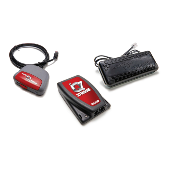
- Page 2 Mouse The AL-KO iQ7 XTREME Controller incorporates a number of unique features The AL-KO iQ7 XTREME Mouse is to designed to maximise the performance of be mounted in the cab of the towing your braking system. vehicle within easy reach of the Auto Detect driver.
-
Page 3: Installation
Wiring Loom The AL-KO iQ7 XTREME Wiring Loom has been specially designed to Figure 1. Generic Wiring Diagram INSTALLATION the connector, it is suggested that an appropriate corrosion preventative Towing Vehicle compound be applied to conductive Figure 2. Socket Wiring... -
Page 4: Fault Signals
Power and earth supplies must come direct vehicle from the battery. This should ensure that the iQ7 Pad AL-KO iQ7 XTREME controller is independent voltage at the tow vehicle battery. of the vehicles electronics. trailer connected, apply the trailer brakes so as to engage operation of the www.alko.com.au... - Page 5 TESTING apply the brakes take note of the braking Hydraulic AL-KO iQ7 Actuator only proportionality between the towing After the Initialisation sequence has been vehicle and the towed vehicle. If they are completed, test the system set-up as follows: not similar then adjust the gain slider to the right for more trailer braking or left a) Turn on the ignition.
- Page 6 UNDER NO CIRCUMSTANCES SHOULD THE ELECTRIC BRAKE WIRE (BLUE) BE CONNECTED TO THE 12 PIN SOCKET. Pin No. Colour Function 12 Volt Power Supply (+ve) Black Earth (-ve) Brown Fault Signal Blue Control Voltage INITIALISATION SEQUENCE Note: If the maximum brake pressure The object of the initialisation calibration is set too high, sequence is to establish minimum...
-
Page 7: Brake Light
5.5mm holes circuit breaker through the brake pedal as indicated on the template. 12 Pin Socket 3. Attach the AL-KO iQ7 pad to the brake 12 volt battery Figure 4. iQ7 Pad iQ7 Pad Ignition Supply The yellow wire labelled “Ignition... - Page 8 Pad MAINTENANCE Remove the outer surface of the adhesive tape on the back of the AL-KO iQ7 mouse. The AL-KO iQ7 is an intelligent trailer Firmly secure to the dashboard of the towing braking system. vehicle in a position that is within easy reach...
- Page 9 AL-KO will bear the cost of the transport of the also void this product warranty. Product to and from AL-KO or the authorised...
-
Page 10: Further Information
1 Airpark Drive, Airport Oaks, Mangere, Auckland Phone: (09) 255 5611 Fax: (09) 255 5612 NO PART OF THIS DOCUMENT MAY BE REPRODUCED WITHOUT AL-KO’S PERMISSION. ALL PART NUMBERS, DIMENSIONS AND SPECIFICATIONS IN THIS DOCUMENT ARE SUBJECT TO CHANGE WITHOUT NOTICE. - Page 11 Template for SB06 AUTO PEDAL Template for SB05 MANUAL PEDAL...
- Page 12 1 Airpark Drive, Airport Oaks, Mangere, Auckland Phone: (09) 255 5611 Fax: (09) 255 5612 NO PART OF THIS DOCUMENT MAY BE REPRODUCED WITHOUT AL-KO’S PERMISSION. ALL PART NUMBERS, DIMENSIONS AND SPECIFICATIONS IN THIS DOCUMENT ARE SUBJECT TO CHANGE WITHOUT NOTICE.
Need help?
Do you have a question about the IQ7 XTREME and is the answer not in the manual?
Questions and answers