
Subscribe to Our Youtube Channel
Related Manuals for prodelin 1132 Series


Summary of Contents for prodelin 1132 Series
- Page 1 4096-630 August12, 2003 ASSEMBLY MANUAL Revision E 1.2M Ku-BAND Rx/Tx SERIES 1132 ANTENNA SYSTEM PRODELIN CORPORATION 1500 Prodelin Drive Newton NC 28658...
- Page 2 1.2M Ku-BAND Rx/Tx SERIES 1132 ANTENNA SYSTEM Revised Az/El to 0185-492 10/12/04 Revised for new reflector 9/3/2003 Revised text on page 14 8/26/02 Revised Diagrams and Text 1/25/02 Revised Address 1/9/02 ORIGINAL RELEASE 3/14/01 REV. DESCRIPTION DATE APPROVED...
- Page 3 4096-630 PRODELIN CORPORATION 1.2M Ku-BAND Rx/Tx SERIES 1132...
-
Page 4: Table Of Contents
4096-630 PRODELIN CORPORATION 1.2M Ku-BAND Rx/Tx SERIES 1132 TABLE OF CONTENTS SECTION TITLE INTRODUCTION GENERAL INFORMATION UNPACKING & INSPECTION FREIGHT DAMAGE MATERIAL MISSING OR DAMAGED MECHANICAL INSTALLATION TOOLS FOUNDATION INTERFACE ANTENNA SYSTEM ASSEMBLY REFLECTOR & SUPPORT ASM PART LIST ANTENNA ASSEMBLY... -
Page 5: Introduction
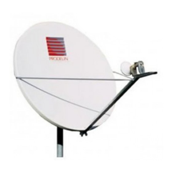
GENERAL INFORMATION This manual describes the assembly and installation of Prodelin's 1.2 meter antenna system. The Prodelin 1.2 meter is a rugged and reliable mount which will operate in the Ku-Band frequency with high efficiency and at the same time successfully withstand the effects of the environment. -
Page 6: Mechanical Installation Tools
The required interface from the foundation to the mount is 2-1/2" schedule 40 pipe (2.88" O.D.). A suggested in-ground foundation is shown in Figure 1. Also available from Prodelin, as options, are a kingpost pedestal mount and a non penetrating mast mount. - Page 7 Minimum depth as shown or extend to local frost line. Foundation meets the design requirements as set forth by the uniform building code. (1982 edition) (PRODELIN CORPORATION DOES NOT REPRESENT OR WARRANT THAT ANY PARTICULAR DESIGN OR SIZE OF FOUNDATION IS APPROPRIATE FOR ANY LOCALITY OR EARTH STATION INSTALLATION.)
- Page 8 4096-630 PRODELIN CORPORATION 1.2M Ku-BAND Rx/Tx SERIES 1132 SECTION II REFLECTOR AND SUPPORT ASSEMBLY REFLECTOR AND SUPPORT ASSEMBLY PART LIST- TABLE 2.0 ITEM PART NO. DESCRIPTION VARIES 1.2M Reflector 0185-492 Az/El Positioner Assembly Hi - Lo Screw 8319-006...
-
Page 9: Antenna System Assembly
4096-630 PRODELIN CORPORATION 1.2M Ku-BAND Rx/Tx SERIES 1132 ANTENNA ASSEMBLY CAUTION: During the assembly procedure, the sequence of instructions must be followed. Do Not Tighten Any Hardware Until Instructed. Refer to the parts list table and the referenced steps. STEP 1. - Page 10 4096-630 PRODELIN CORPORATION 1.2M Ku-BAND Rx/Tx SERIES 1132 FEED SUPPORT PARTS LIST - TABLE 2.2 ITEM NO. PART NO. DESCRIPTION VARIES Feed Rod VARIES Feed Support Tube 5 / 16” x 1.00” Bolt 8031-008 5 / 16” x 3.25” Bolt...
-
Page 11: Feed Support Assembly
4096-630 PRODELIN CORPORATION 1.2M Ku-BAND Rx/Tx SERIES 1132 FEED SUPPORT ASSEMBLY These instructions are intended as a general reference for feed support assembly. If your antenna system has specific feed support installation instructions, then refer to them at this time. - Page 12 4096-630 PRODELIN CORPORATION 1.2M Ku-BAND Rx/Tx SERIES 1132 STEP 3. A). Connect the feed rods to the feed support tube with ( items: 4, 6, 7 ) and with [ 2 ] of ( item 5 ). Feed Support Tube STEP 4.
-
Page 13: Antenna Pointing
Note: The following alignment procedure is intended only as a general reference guide for this antenna. For proper antenna performance, accurate alignment is critical. Therefore, it is recommended that your own detailed procedure be used or contact Prodelin’s Technical Support Department for additional recommendations. STEP 1:... - Page 14 4096-630 PRODELIN CORPORATION 1.2M Ku-BAND Rx/Tx SERIES 1132 ‘A side’ Scale not used on this system Reflector Support Elevation Adjustment Bolt Tighten canister after rough ‘B side’ scale adjustment for elevation adjustment Fine azimuth LOOSEN THIS BEFORE adjustment ELEVATION ADJUSTMENT TYPICAL BOTH SIDES FIGURE 2.
-
Page 15: Maintenance
It is only necessary to inspect for any physical damage done by vandalism or very severe weather conditions. Should any damage be detected to a portion of the reflector, contact the Customer Service Department at Prodelin for recommendations involving reflector repair. MOUNT AND REFLECTOR SUPPORT STRUCTURE The mount and reflector support structure supplied with this antenna is of steel construction and has a powder painted finish.
Need help?
Do you have a question about the 1132 Series and is the answer not in the manual?
Questions and answers