
Subscribe to Our Youtube Channel
Related Manuals for prodelin 1134


Summary of Contents for prodelin 1134
-
Page 1: Antenna System
4096-393 August 21, 1997 Revision D ASSEMBLY MANUAL 1.2M Ku-BAND Rx/Tx SERIES 1134 ANTENNA SYSTEM PRODELIN CORPORATION... - Page 2 1.2M Ku-BAND Rx/Tx SERIES 1134 ANTENNA SYSTEM Revised per ECN2246 082197 Updated 3/18/97 Revised for back structure modification 9/16/96 Revise pgs. 5,7,8; Step 6, pg. 13. Figure 1 and 3 for 5/1/96 R Frye clarity. ORIGINAL RELEASE 01/10/95 R Frye REV.
-
Page 3: Prodelin Corporation 1.2M Ku-Band Rx/Tx Series
4096-393 PRODELIN CORPORATION 1.2M Ku-BAND Rx/Tx SERIES 1134... -
Page 4: Table Of Contents
4096-393 PRODELIN CORPORATION 1.2M Ku-BAND Rx/Tx SERIES 1134 TABLE OF CONTENTS SECTION TITLE INTRODUCTION GENERAL INFORMATION UNPACKING & INSPECTION FREIGHT DAMAGE MATERIAL MISSING OR DAMAGED MECHANICAL INSTALLATION TOOLS FOUNDATION INTERFACE ANTENNA SYSTEM ASSEMBLY ANTENNA ASSEMBLY FEED ASSEMBLY SATELLITE ALIGNMENT ANTENNA POINTING... -
Page 5: General Information
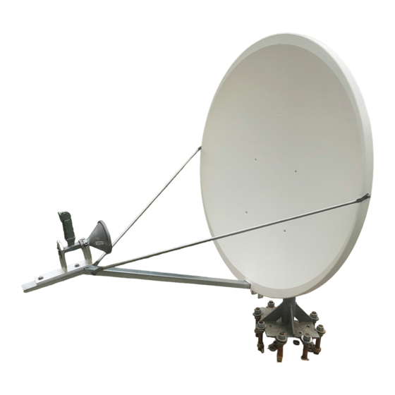
This manual describes the assembly and installation of Prodelin's 1.2 meter antenna system. The Prodelin 1.2 meter is a rugged and reliable mount which will operate in the Ku-Band frequency with high efficiency and at the same time successfully withstand the effects of the environment. -
Page 6: Mechanical Installation Tools
The required interface from the foundation to the mount is 2-1/2" schedule 40 pipe (2.88" or 7.3 cm O.D.). A suggested in-ground foundation is shown in Figure 1. Also available from Prodelin, as options, are a kingpost pedestal mount and a non penetrating mast mount. - Page 7 Minimum depth as shown or extend to local frost line. Foundation meets the design requirements as set forth by the uniform building code. (1982 edition) (PRODELIN CORPORATION DOES NOT REPRESENT OR WARRANT THAT ANY PARTICULAR DESIGN OR SIZE OF FOUNDATION IS APPROPRIATE FOR ANY LOCALITY OR EARTH STATION INSTALLATION.)
- Page 8 4096-393 PRODELIN CORPORATION 1.2M Ku-BAND Rx/Tx SERIES 1134 PARTS LIST - 1.2M ANTENNA ASSEMBLY ITEM NO. PART NO. DESCRIPTION 0181-585 Canister Assembly 0181-584 Mount Assembly VARIES 1.2M Reflector 0490-203 Elevation Rod 1 / 2 - 13 Hex Nut 8104-007 Hi - Lo Screw 8319-006 5 / 16”...
-
Page 9: Antenna System Assembly
4096-393 PRODELIN CORPORATION 1.2M Ku-BAND Rx/Tx SERIES 1134 SECTION II ANTENNA ASSEMBLY CAUTION: During the assembly procedure, the sequence of instructions must be followed. Do Not Tighten Any Hardware Until Instructed . Refer to the antenna assembly parts list and the steps shown below. -
Page 10: Canister Assembly
4096-393 PRODELIN CORPORATION 1.2M Ku-BAND Rx/Tx SERIES 1134 STEP 3; Remove A). Remove rotation bolt, washer & lock washer and set aside. Remove B). Remove [1] 1 / 2” jam nut. Azimuth Rod Canister Assembly STEP 4: Azimuth Rod A). Slide azimuth tube ( from Step. 1 ) onto azimuth rod. -
Page 11: Mount Assembly
4096-393 PRODELIN CORPORATION 1.2M Ku-BAND Rx/Tx SERIES 1134 6.0” STEP 6: (15.2 cm) A). Thread 1 / 2” nut (item 5) approximately 6” (15.2 cm) onto elevation rod. Elevation Rod [ 5 ] STEP 7: A). Insert elevation rod thru hole in elevation channel on mount assembly. - Page 12 4096-393 PRODELIN CORPORATION 1.2M Ku-BAND Rx/Tx SERIES 1134 STEP 9: A). Place the 1.2 meter reflector face down Mount Assembly on a flat surface. B). Place the mount assembly onto the back of the reflector and orient as shown. Bottom of reflector C).
- Page 13 4096-393 PRODELIN CORPORATION 1.2M Ku-BAND Rx/Tx SERIES 1134 Hardware STEP 11: (Step 1) A). Adjust azimuth tube so that the tube will fit into the hole on the reflector mount assembly. B). Secure azimuth tube to the mount assembly with hardware set aside in Step 1.
-
Page 14: X 1.00" Bolt
4096-393 PRODELIN CORPORATION 1.2M Ku-BAND Rx/Tx SERIES 1134 2.1 FEED SUPPORT ASSEMBLY These instructions are intended as a general reference for feed support assembly. If your antenna system has specific feed support installation instructions, then refer to them at this time. - Page 15 4096-393 PRODELIN CORPORATION 1.2M Ku-BAND Rx/Tx SERIES 1134 CAUTION: During the assembly procedure, the sequence of instructions must be followed. Do Not Tighten Any Hardware Until Instructed. Refer to the feed support parts list and the steps shown below. STEP 1: A).
- Page 16 4096-393 PRODELIN CORPORATION 1.2M Ku-BAND Rx/Tx SERIES 1134 STEP 3: STEP 3: A). Connect the feed rods to the feed support tube with ( items: 4, 6, 7 ) and with [ 2 ] of ( item 5 ). Feed Rod...
- Page 17 4096-393 PRODELIN CORPORATION 1.2M Ku-BAND Rx/Tx SERIES 1134 DETAIL A [ 5 ] [ 5, 6, 7 ] [ 7 ] Reflector DETAIL B Feed Rod Feed Support Brackets Feed Support Tube [ 5, 6, 7 ] [ 5, 6, 7 ]...
-
Page 18: Antenna Pointing
4096-393 PRODELIN CORPORATION 1.2M Ku-BAND Rx/Tx SERIES 1134 SECTION III ANTENNA POINTING 3.0 ANTENNA POINTING The 1.2 meter reflector contains a 17.3° elevation offset look angle. Therefore, when the reflector aperture is perpendicular to the ground, the antenna is actually looking 17.3°... - Page 19 4096-393 PRODELIN CORPORATION 1.2M Ku-BAND Rx/Tx SERIES 1134 PLACE INCLINOMETER HERE ADJUST ELEVATION ADJUST AZIMUTH Figure 2...
-
Page 20: Maintenance
REFLECTOR Prodelin's reflector does not require any maintenance. The composite construction of the reflector is virtually impervious to any damages that could be caused by weather or atmospheric conditions. -
Page 21: Feed & Feed Support
4096-393 PRODELIN CORPORATION 1.2M Ku-BAND Rx/Tx SERIES 1134 FEED AND FEED SUPPORT The feed support and feed rods should be inspected to insure that all hardware is secure. The feed/radio mounting bolts should be tight. The feed horn window should be inspected to insure that it is intact so that no moisture... -
Page 22: Flat Washer
4096-393 PRODELIN CORPORATION 1.2M Ku-BAND Rx/Tx SERIES 1134 Prodelin Corporation Box contents for 1134 series, 1.2M .8 F/D, basic antenna (Options to basic antenna not listed) Description 0800-1366 1.2M .8 F/D Az/EL mount 0181-584 assy, reflector support, 1.2M, .8 F/D 0181-585 assy, canister, 1.2M, .8 F/D...
Need help?
Do you have a question about the 1134 and is the answer not in the manual?
Questions and answers