
Related Manuals for prodelin 1251


Summary of Contents for prodelin 1251
- Page 1 4096-476 November 21, 1997 Revision B Assembly Manual 2.4 METER SERIES 1251 ANTENNA SYSTEM PRODELIN CORPORATION 1700 NE CABLE DRIVE CONOVER, NC 28613-0368...
- Page 2 4096-476 PRODELIN CORPORATION 2.4M SERIES 1251 2.4 Meter 2 Piece Az/El Installation Instructions Overall Update 11/21/97 Revised Hdw tables to reflect B.O.M 2/11/97 ORIGINAL RELEASE 4/10/96 REV. DESCRIPTION DATE APPROVED...
-
Page 3: Table Of Contents
4096-476 PRODELIN CORPORATION 2.4M SERIES 1251 2.4M SERIES 1251 ANTENNA SYSTEM TABLE OF CONTENTS SECTION TITLE GENERAL INFORMATION INTRODUCTION UNPACKING AND INSPECTION MECHANICAL INSTALLATION TOOLS SITE SELECTION SUGGESTED MAST & FOUNDATION REFLECTOR AND SUPPORT ASSEMBLY PART LIST AZ/EL POSITIONER INSTALLATION... - Page 4 4096-476 PRODELIN CORPORATION 2.4M SERIES 1251...
-
Page 5: Prodelin Corporation
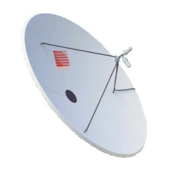
This manual describes the assembly and installation of Prodelin's 2.4M 2-Piece Rx/Tx offset antenna system with an Az/El mount (series number1251). The Prodelin 2.4M is a rugged, reliable antenna system that will operate at C-band and Ku-band frequencies with high efficiency and at the same time successfully withstand the effects of the environment. -
Page 6: Mechanical Installation Tools
4096-476 PRODELIN CORPORATION 2.4M SERIES 1251 MECHANICAL INSTALLATION TOOLS HARDWARE SIZE SAE WRENCH METRIC WRENCH MAXIMUM REC. SIZE SIZE TORQUE 3 / 8” 9/16” 14 mm 15 ft-lbs 1 / 2” 3 / 4” 20 mm 35 ft-lbs 5 / 8”... - Page 7 Minimum depth as shown or extend to local frost line. Foundation meets the design requirements as set forth by the uniform building code. (1982 edition) (PRODELIN CORPORATION DOES NOT REPRESENT OR WARRANT THAT ANY PARTICULAR DESIGN OR SIZE OF FOUNDATION IS APPROPRIATE FOR ANY LOCALITY OR EARTH STATION INSTALLATION.)
-
Page 8: Reflector And Support Assembly
4096-476 PRODELIN CORPORATION 2.4M SERIES 1251 SECTION II REFLECTOR AND SUPPORT ASSEMBLY REFLECTOR AND SUPPORT ASSEMBLY PART LIST- TABLE 2.0 ITEM PART NO. DESCRIPTION 0179-381 REFLECTOR “A” SIDE 0179-383 REFLECTOR “A” SIDE – WITH SHC 0179-382 REFLECTOR “B” SIDE 0179-384 REFLECTOR “B”... - Page 9 4096-476 PRODELIN CORPORATION 2.4M SERIES 1251 PARTS LIST - CONTINUED ITEM PART NO. DESCRIPTION 3/4” HEX NUT 8106-007 1/2” FLATWASHER 8201-043 1/2” FLATWASHER - NARROW 8201-030 8202-043 1/2” LOCK WASHER 1/2” HEX NUT 8104-007 1/2”-13 x 1.25 BOLT 8033-010...
-
Page 10: Az/El Positioner Installation
4096-476 PRODELIN CORPORATION 2.4M SERIES 1251 PARTS LIST - CONTINUED ITEM PART NO. DESCRIPTION 1/2”-13 x 2.50 BOLT 8033-021 8033-032 1/2”-13 x 4.00 BOLT 8201-042 3/8” FLATWASHER 3/8” LOCK WASHER 8202-042 3/8”-16 x 1.25 HEX 8032-010 CAUTION : During the assembly procedure, the sequence of instructions must be followed. - Page 11 4096-476 PRODELIN CORPORATION 2.4M SERIES 1251 STEP 1: Back out the [8] 5/8” set screws from the canister and slip Az/El positioner assembly over the mast pipe. Tighten the set screws snug against the mast pipe. Az/El Positioner Asm 5/8” Set Screws...
- Page 12 4096-476 PRODELIN CORPORATION 2.4M SERIES 1251 Canister Plate STEP 4: Adjustment Tube Place the end of the azimuth rod thru the adjustment tube attached to the top of the canister plate and replace the 1” hex nut. Azimuth Rod 1” Hex nut...
-
Page 13: Reflector Petal Orientation
2.4M SERIES 1251 REFLECTOR PETAL ORIENTATION The series 1251 reflector petals are labeled “A” and “B”. In the standard upright position, the antenna elevation angle range is between 5 and 90 degrees. When viewed from behind in the standard position (feed support at the bottom), the “A”... -
Page 14: Reflector Support Assembly
4096-476 PRODELIN CORPORATION 2.4M SERIES 1251 Feed Support on Top “B” Petal “A” Petal ( item 2 ) ( item 1 ) Feed Rod Holes Center of Reflector Figure 2 Orientation of Angled Crossarm for Standard Position Orientation of Angled... - Page 15 4096-476 PRODELIN CORPORATION 2.4M SERIES 1251 STEP 1: Reflector Petal Place three of the threaded inserts (item 4) thru the face of each reflector petal (items 1& 2) and secure with 3/4” hardware (items 9, 10 & 11). Snug [ 4 ] only, Do not completely tighten at this time.
- Page 16 4096-476 PRODELIN CORPORATION 2.4M SERIES 1251 Attach the top and bottom crossarms (item 6) to the reflector support tube with 1/2” hardware (items 12,14,15,17). Note orientation of crossarms. Do not tighten. [ 6 ] 2 PL [ 17, 12 ] 4 PL...
- Page 17 4096-476 PRODELIN CORPORATION 2.4M SERIES 1251 Petal Petal [ 13, 14, 15 ] [ 16,13 ] STEP 6: Locate the elevation assembly (item 7) 1” Hex Nut and remove the 3/4” hardware as well & as one 1” hex nut and washer.
-
Page 18: Feed Support
4096-476 PRODELIN CORPORATION 2.4M SERIES 1251 Support Tube 3/4” Hardware Elevation Assembly STEP 9: [ 19, 20, 21 ] A) Attach the angled crossarm (item 8) to the reflector support Support Tube tube in either the standard or inverted position depending on the reflector orientation with 1/2”... -
Page 19: Feed Support Installation
4096-476 PRODELIN CORPORATION 2.4M SERIES 1251 The following instructions are for installing a typical C-band or Ku-band feed support to Prodelin's 2.4 meter antenna system. FEED SUPPORT PART LIST- TABLE 3.0 ITEM PART NO. DESCRIPTION VARIES FEED SUPPORT VARIES FEED ROD – Ku BAND VARIES FEED ROD –... - Page 20 4096-476 PRODELIN CORPORATION 2.4M SERIES 1251 Attach the feed rods loosely to the reflector with 3/8” hardware (items- 4, 6, 7 & 8 ). See detail A Feed Rods See Detail A STEP 2: Position the feed support in front of the reflector and attach to the ends of the two feed rods with 3/8”...
- Page 21 4096-476 PRODELIN CORPORATION 2.4M SERIES 1251 Lift the end of the feed support tube and attach to the bottom of the reflector with 3/8’ hardware (items – 4, 6, 7 & 8). See Detail C. Tighten all feed support hardware at this time.
- Page 22 4096-476 PRODELIN CORPORATION 2.4M SERIES 1251 Feed Rods [ 5, 6 ] [ 6, 7, 8 ] Feed Support Tube DETAIL B DETAIL C [ 6, 7, 8 ] Feed Support Tube Reflector [ 4 ] NOTE: At this time you are ready to install your C-band or Ku-band feed system. For feed installation, reference any instructions that are enclosed with your specific feed support.
-
Page 23: Antenna Pointing
For proper antenna performance, accurate alignment is critical. Therefore, it is recommended that your own detailed procedure be used or contact Prodelin’s Technical Support Department for additional recommendations. Initial Alignment Place an inclinometer on the reflector support as shown in Figure 4. - Page 24 4096-476 PRODELIN CORPORATION 2.4M SERIES 1251 Look Angle Inclinometer 22.3 Elevation Adjustment Azimuth Adjustment Figure 4...
-
Page 25: Maintenance
It is only necessary to inspect for any physical damage done by vandalism or very severe weather conditions. Should any damage be detected to a portion of the reflector, contact the Customer Service Department at Prodelin for recommendations involving reflector repair. -
Page 26: Mount And Reflector Support
4096-476 PRODELIN CORPORATION 2.4M SERIES 1251 Mount And Reflector Support Structure The mount and reflector support structure supplied with this antenna is of steel construction and has a hot-dipped galvanized finish. If inspection shows any signs of structural failure, the mount members that are damaged should be repaired or replaced.
Need help?
Do you have a question about the 1251 and is the answer not in the manual?
Questions and answers