
Subscribe to Our Youtube Channel
Related Manuals for prodelin 1183 series


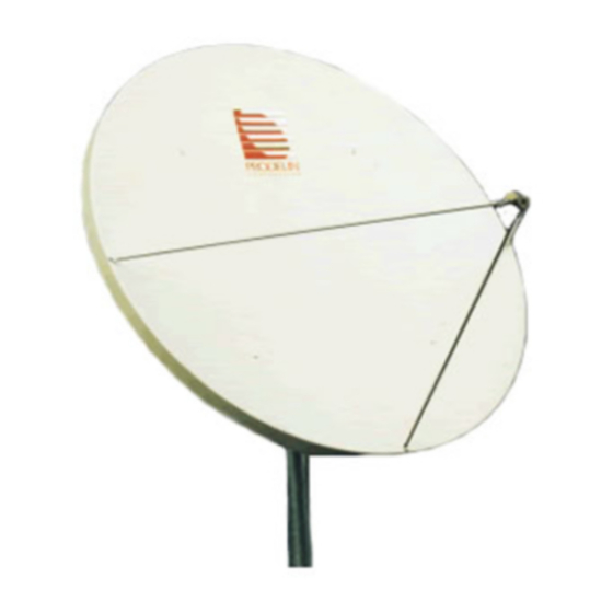
Summary of Contents for prodelin 1183 series
- Page 1 4096-291 REVISION E August 3, 1998 ASSEMBLY MANUAL 1.8 METER SERIES 1183 Rx/O Az/El MOUNT ANTENNA SYSTEM PRODELIN CORPORATION 1700 NE CABLE DRIVE...
- Page 2 4096-291 PRODELIN CORPORATION 1.8M SERIES 1183 CONOVER, NC 28613-0368 1.8 METER SERIES 1183 STEM Rx/O Az/El MOUNT ANTENNA SY Updated Manual 08/03/98 Revised Canister assembly per ECN 1837 7/14/98 Revised antenna asm parts list, It. 8&9 were qty 06/10/97 P.G.W.
-
Page 3: Table Of Contents
4096-291 PRODELIN CORPORATION 1.8M SERIES 1183 REV. DESCRIPTION DATE APPROVED 1.8M SERIES 1183 ANTENNA SYSTEM TABLE OF CONTENTS SECTION TITLE GENERAL INFORMATION Introduction Unpacking And Inspection Freight Damage Missing Or Damaged Material Suggested Tool List Mechanical Alignment Tools Site Selection Suggested Mast &... - Page 4 4096-291 PRODELIN CORPORATION 1.8M SERIES 1183...
- Page 5 4096-291 PRODELIN CORPORATION 1.8M SERIES 1183...
-
Page 6: General Information
INTRODUCTION This manual describes the assembly and installation of Prodelin's 1.8M Rx/O antenna system with an Az/El mount (series number 1183). The Prodelin 1.8M is a rugged, reliable antenna system, which will operate with high efficiency and at the same time successfully withstand the effects of the environment. The basic 1.8 meter Rx/O antenna consists of an offset reflector, reflector support,... -
Page 7: Mechanical Alignment Tools
4096-291 PRODELIN CORPORATION 1.8M SERIES 1183 The following tools are suggested for the antenna installation . HARDWARE SIZE SAE WRENCH METRIC WRENCH MAXIMUM REC. SIZE SIZE TORQUE 7/16" 11mm 49 in-lbs 1/4" BOLT 5/16" BOLT 1/2" 13 mm 12 ft-lbs 3/8”... - Page 8 The antenna should be properly grounded to meet applicable local codes. Minimum depth as shown or extend to local frost line. (PRODELIN CORPORATION DOES NOT REPRESENT OR WARRANT THAT ANY PARTICULAR DESIGN OR SIZE OF FOUNDATION IS APPROPRIATE FOR ANY LOCALITY OR EARTH STATION INSTALLATION.)
- Page 9 4096-291 PRODELIN CORPORATION 1.8M SERIES 1183 PARTS LIST - 1.8M ANTENNA ASSEMBLY ITEM PART NO. DESCRIPTION 0179-191 1.8M REFLECTOR 0181-452 CANISTER & POSITIONER ASSEMBLY 0211-417 REFLECTOR CROSS ARMS 1 / 2” x 1.50” CARRIAGE BOLT 8043-014 8104-007 1 / 2” HEX NUT 1 / 2”...
-
Page 10: Antenna Assembly
4096-291 PRODELIN CORPORATION 1.8M SERIES 1183 ITEM PART NO. DESCRIPTION 8032-036 3 / 8” x 4.5” HEX BOLT 8032-040 3 / 8” x 5.0” HEX BOLT 3 / 8” HEX NUT 8102-007 3 / 8” LOCK WASHER 8202-042 3 / 8” WASHER... - Page 11 4096-291 PRODELIN CORPORATION 1.8M SERIES 1183 STEP 1: Loosen the six 1/2 set screws on the canister (item 2) and slip the canister /positioner assembly onto the mast pipe, orient toward the satellite, and snug the set screws. Canister/Positioner Assembly 1/2"...
-
Page 12: Feed Support Assembly
4096-291 PRODELIN CORPORATION 1.8M SERIES 1183 Locate the top of the reflector and insert (2) 5” bolts ( item 9 ) thru top two inner most holes on face of reflector as shown. [ 5 ] STEP 4: Top of Reflector A). - Page 13 4096-291 PRODELIN CORPORATION 1.8M SERIES 1183 These instructions are intended as a general reference for feed support assembly. If your antenna system has specific feed or feed support installation instructions, please refer to them at this time. PARTS LIST - 1.8M FEED SUPPORT ITEM NO.
- Page 14 4096-291 PRODELIN CORPORATION 1.8M SERIES 1183 ITEM PART NO. DESCRIPTION 8030-006 1/4” x .75” Hex Bolt 1/4” Lockwasher 8202-040 1/4" Hex Nut 8102-007 CAUTION: During the assembly procedure, the sequence of instructions must be followed . Do Not Tighten Any Hardware Until Instructed.
- Page 15 4096-291 PRODELIN CORPORATION 1.8M SERIES 1183 STEP 2: Attach the bottom feed rod (item 3) to the bottom of the reflector with (items 7,9,10). and with (2) of (item 8). Do not tighten. See Detail B. Bottom Feed Rod See Detail B...
- Page 16 LNB (single pole) using the screws provided with the LNB or to the OMT (dual pole) using the o-ring and screws Feed Horn provided by Prodelin. B) Place the feed assembly into the saddle of the feed bracket (item 4) as shown, Feed Bracket...
-
Page 17: Antenna Pointing
4096-291 PRODELIN CORPORATION 1.8M SERIES 1183 DETAIL A [ 7, 8 ] Feed [ 8, 9, 10 ] Reflector DETAIL B Feed Rod- Bottom [ 8, 9, 10 ] [ 7, 8 ] Bottom of Reflector SECTION IV ANTENNA POINTING... -
Page 18: Alignment To Satellite
4096-291 PRODELIN CORPORATION 1.8M SERIES 1183 ALIGNMENT TO SATELLITE The 1.8 meter offset reflector contains a 22.3 elevation offset look angle. Therefore, when the reflector aperture is perpendicular to the ground, the antenna is actually looking 22.3 in elevation. The lower back rib on the reflector is a Sight Reference Rib and can be used to read the correct elevation look angle. - Page 19 4096-291 PRODELIN CORPORATION 1.8M SERIES 1183 Elevation Adjustment Inclinometer FIGURE 3...
-
Page 20: Maintenance
Check for corrosion - on the reflector structure and mount. REFLECTOR Prodelin's reflector does not require any maintenance. The composite construction of the reflector is virtually impervious to any damages that could be caused by weather or other atmospheric conditions. -
Page 21: Feed System
4096-291 PRODELIN CORPORATION 1.8M SERIES 1183 The mount and reflector support structure supplied with this antenna is of steel construction and has a hot-dipped galvanized finish. If inspection shows any signs of structural failure, the mount members that are damaged should be repaired or replaced.
Need help?
Do you have a question about the 1183 series and is the answer not in the manual?
Questions and answers