Advertisement
Table of Contents
- 1 Table of Contents
- 2 Unpacking and Inspection
- 3 Mechanical Installation Tools
- 4 Pedestal Foundation
- 5 Az/El Positioner Installation
- 6 Reflector Support Assembly
- 7 Feed Support Installation
- 8 C-Band Cross-Pol & Co-Pol Feeds
- 9 C-Band Lnb / Lna Attachment
- 10 Initial Alignment
- 11 Periodic Inspection
- 12 Mount & Reflector Support Structure
- Download this manual
Advertisement
Table of Contents

Subscribe to Our Youtube Channel
Related Manuals for prodelin 3.8M


Summary of Contents for prodelin 3.8M
- Page 1 4096-535 Revision J May 13, 2002 ASSEMBLY MANUAL 3.8M C-BAND Rx/Tx ANTENNA SYSTEM PRODELIN CORPORATION 1500 Prodelin Drive Newton NC 28658...
- Page 2 4096-535 PRODELIN CORPORATION 3.8M C-BAND Rx/Tx ANTENNA SYSTEM 3.8M C-BAND Rx/Tx ANTENNA SYSTEM Revised Added 0168-260 Spacers 10/7/04 Revise Labeling Text 5/13/02 Revised Address 1/22/02 Revise Figure 8 page 29 10-6-00 Revise Part Numbers Page 9 6-21-00 Revised to delete Ku-Band features...
-
Page 3: Table Of Contents
4096-535 PRODELIN CORPORATION 3.8M C-BAND Rx/Tx ANTENNA SYSTEM 3.8 METER C-BAND Rx/Tx ANTENNA SYSTEM TABLE OF CONTENTS SECTION TITLE GENERAL INFORMATION INTRODUCTION UNPACKING AND INSPECTION MECHANICAL INSTALLATION TOOLS SITE SELECTION MAST AND FOUNDATION IN-GROUND MAST PEDESTAL FOUNDATION REFLECTOR AND SUPPORT ASSEMBLY... - Page 4 4096-535 PRODELIN CORPORATION 3.8M C-BAND Rx/Tx ANTENNA SYSTEM...
-
Page 5: Unpacking And Inspection
INTRODUCTION This manual describes the assembly and installation of Prodelin's 3.8M C-Band Rx/Tx antenna system The Prodelin 3.8M is a rugged, reliable antenna system that will operate at C-band frequencies with high efficiency and at the same time successfully withstand the effects of the environment. -
Page 6: Mechanical Installation Tools
4096-535 PRODELIN CORPORATION 3.8M C-BAND Rx/Tx ANTENNA SYSTEM MECHANICAL INSTALLATION TOOLS HARDWARE SIZE SAE WRENCH METRIC WRENCH MAXIMUM REC. SIZE SIZE TORQUE 1 / 4” 7 / 16” 11 mm 80 in-lbs 5 / 16” 1 / 2” 13 mm 140 in-lbs 3 / 8”... -
Page 7: Pedestal Foundation
SECTION II SUGGESTED MAST AND FOUNDATIONS NOTE: Due to the wide variety of soil conditions, Prodelin Corporation does not warrant that any particular design or size of foundation is appropriate for any locality or earth station installation. It is the responsibility of the installer/user to determine if it meets the site/locality requirements. - Page 8 THE ANTENNA SHOULD BE PROPERLY GROUNDED TO MEET APPLICABLE LOCAL CODES. MINIMUM DEPTH AS SHOWN OR EXTENDED TO LOCAL FROST LINE. (PRODELIN CORP. DOES NOT REPRESENT OR WARRANT THAT ANY PARTICULAR DESIGN OR SIZE OF FOUNDATION IS APPROPRIATE FOR ANY LOCALITY OR EARTH STATION INSTALLATION.)
- Page 9 4096-535 PRODELIN CORPORATION 3.8M C-BAND Rx/Tx ANTENNA SYSTEM PEDESTAL FOUNDATIONS FOUNDATION PART LIST ITEM NO. PART NO. DESCRIPTION 0490-285 3.8M PEDESTAL MAST PIPE 8107-007 1-8 HEX NUT 8201-049 1" FLATWASHER 8202-046 1" LOCKWASHER 0180-238 1 - 8 X 36" ANCHOR ROD...
- Page 10 4096-535 PRODELIN CORPORATION 3.8M C-BAND Rx/Tx ANTENNA SYSTEM [ 1 ] 1-1/2” Grout Leveling (if required) [ 5 ] [ 2, 3, 4 ] 4.0” [ 2, 3 ] 30.0” 27.0” [ 2, 3, 2 ] 3.0” MIN (TYP) Figure 2.
- Page 11 4096-535 PRODELIN CORPORATION 3.8M C-BAND Rx/Tx ANTENNA SYSTEM SECTION III REFLECTOR AND SUPPORT ASSEMBLY REFLECTOR AND SUPPORT ASSEMBLY PART LIST – TABLE 3.0 ITEM NO. PART NO. DESCRIPTION 0159-273 THREADED INSERT - # 1 0159-272 THREADED INSERT - # 2...
- Page 12 4096-535 PRODELIN CORPORATION 3.8M C-BAND Rx/Tx ANTENNA SYSTEM PART LIST - CONTINUED ITEM NO. PART NO. DESCRIPTION 8202-052 LOCKWASHER, 7/8” 8110-007 NUT, HEX 7/8” 8033-064 BOLT, 1/2 – 13 x 8.00 8033-072 BOLT, 1/2 – 13 x 9.00 8033-096 BOLT, 1/2 – 13 x 12.00 8201-033 FLATWASHER, 1/2”...
-
Page 13: Az/El Positioner Installation
Tighten Securely. REFLECTOR QUADRANT ORIENTATION The 3.8M reflector quadrants can be assembled in either the standard inverted positions. The reflector quadrants are numbered 1, 2, 3 and 4. These numbers can be found on the back of each quadrant embossed into the fiberglass. - Page 14 4096-535 PRODELIN CORPORATION 3.8M C-BAND Rx/Tx ANTENNA SYSTEM Major Axis Center Line of Reflector (Minor Axis) Feed Rod Holes Feed Support Holes Figure 4. (Standard) At Bottom Feed Support Holes At Top Major Axis Feed Rod Holes Center Line of Reflector (Minor Axis) Figure 5.
-
Page 15: Reflector Support Assembly
4096-535 PRODELIN CORPORATION 3.8M C-BAND Rx/Tx ANTENNA SYSTEM REFLECTOR SUPPORT ASSEMBLY WARNING! The reflector support frame includes a precision alignment feature. Do not drop or drag the frame during the installation process. Do not attempt to adjust the round tube spacers in the frame assembly, as these are factory pre-set. - Page 16 4096-535 PRODELIN CORPORATION 3.8M C-BAND Rx/Tx ANTENNA SYSTEM STEP 2: Hardware Locate the crossarms ( item 12 ) and remove the 1/2” hardware & anti-crushtubes. Crossarm Crushtube 1/2 Bolt STEP 3: Crossarms A) Lay the support frame (item 13) on a safe flat surface, being careful not to damage the tube spacers.
- Page 17 4096-535 PRODELIN CORPORATION 3.8M C-BAND Rx/Tx ANTENNA SYSTEM STEP 4: Lift the assembled support frame to the Az/El positioner and secure with 1” hardware ( items 34, 35, 36 ). Lay frame back to rest on positioner. Support Frame [ 34, 35, 36 ]...
- Page 18 4096-535 PRODELIN CORPORATION 3.8M C-BAND Rx/Tx ANTENNA SYSTEM Quadrants Insert Spacer Tube Frame [28, 29 ] [ 29, 30, 31 ] 1/2” Hardware Detail B Detail C STEP 6: A) Position quadrant 3 (quadrant 1 for inverted) to the bottom right side of the frame as shown.
- Page 19 4096-535 PRODELIN CORPORATION 3.8M C-BAND Rx/Tx ANTENNA SYSTEM STEP 7: A) Position quadrant 1 (quadrant 2 for inverted) to the top left side of the frame as shown. B) Place Spacers as in step 5 and Detail C) Secure the quadrant to the frame with 1/2”...
- Page 20 4096-535 PRODELIN CORPORATION 3.8M C-BAND Rx/Tx ANTENNA SYSTEM STEP 9: [ 35, 36, 37 ] Locate the elevation rod (item 14) and secure between the channels on the support frame with 1” hardware (items 34, 35, 36, 37) [ 34, 35 ]...
-
Page 21: Feed Support Installation
4096-535 PRODELIN CORPORATION 3.8M C-BAND Rx/Tx ANTENNA SYSTEM SECTION IV FEED SUPPORT ASSEMBLY FEED SUPPORT PART LIST – TABLE 4.0 ITEM # PART # DESCRIPTION 0176-257 FEED ROD Varies FEED SUPPORT TUBE 8033-026 BOLT, 1/2-13 x 3.25" 8032-012 BOLT, 3/8-16 x 1.50"... - Page 22 4096-535 PRODELIN CORPORATION 3.8M C-BAND Rx/Tx ANTENNA SYSTEM STEP 2: Position the feed support (item 2) in front of the reflector as shown and attach to the to ends of the feed rods with 1/2” hardware (items3, 5, 6, 7).
- Page 23 4096-535 PRODELIN CORPORATION 3.8M C-BAND Rx/Tx ANTENNA SYSTEM [ 8, 9, 10 ] [ 4, 8 ] Reflector DETAIL D Feed Rod Feed Rods [ 3, 5 ] Feed Support Tube [ 5, 6, 7 ] DETAIL E [ 8, 9, 10 ]...
-
Page 24: C-Band Cross-Pol & Co-Pol Feeds
3.8M C-BAND Rx/Tx ANTENNA SYSTEM C-BAND CROSS-POL AND CO-POL FEEDS Prodelin 3.8m Rx/Tx antenna system is available in Cross-pol, or Co-pol feed assemblies with type "N" or "WR137" connectors. Refer to figure 6, the parts list for this section and follow the instructions in the listed sequence C-BAND CROSS-POL &... - Page 25 4096-535 PRODELIN CORPORATION 3.8M C-BAND Rx/Tx ANTENNA SYSTEM Attach the bottom feed mounting bracket (item 2) to the feed support tube with four [4] 3/8-16 x 1.25" bolts, four [4] 3/8" lockwashers, and four [4] 3/8-16 hex nuts (items 4,5,6) as shown. Tighten securely.
- Page 26 3.8M C-BAND Rx/Tx ANTENNA SYSTEM C-BAND CIRCULAR POLARIZED FEED INSTALLATION ( 1.09 VAR ) Prodelin 3.8m Rx/Tx antenna system is available in Left Hand or Right Hand Circular Polarized feed assemblies with type "N" or "WR137" connectors. Note that the sense of polarization is relative to the transmit band of the feed assembly and not the antenna system.
- Page 27 4096-535 PRODELIN CORPORATION 3.8M C-BAND Rx/Tx ANTENNA SYSTEM Refer to the part list and figure 7 for this section. Follow the instructions in the listed sequence. Do not tighten any hardware until instructed. Place feed mounting bracket (item 2) on the feed support and attach with 5/16-18 x 1.00 bolts, flatwashers, lockwashers and hex nuts (items 5,6,7,8).
- Page 28 4096-535 PRODELIN CORPORATION 3.8M C-BAND Rx/Tx ANTENNA SYSTEM [ 10, 11, 12 ] [ 9, 11, 12 ] Small Opening ( 2.75 Dia ) [ 3 ] [ 4 ] [ 1 ] POLARIZER [ 5, 8 ] Transmit 2 PL...
- Page 29 4096-535 PRODELIN CORPORATION 3.8M C-BAND Rx/Tx ANTENNA SYSTEM C-BAND CIRCULAR POLARIZED FEED INSTALLATION ( 1.3 VAR ) C-BAND CIRCULAR POLARIZED FEED ASM PART LIST (1.3 VAR) ITEM NO. PART NO. DESCRIPTION 0183-317 FEED HORN 0183-341 CROSS-POL OMT 0182-191 CIRCULAR POLARIZER...
- Page 30 4096-535 PRODELIN CORPORATION 3.8M C-BAND Rx/Tx ANTENNA SYSTEM Refer to the part list and figure 8 for this section. Follow the instructions in the listed sequence. Do not tighten any hardware until instructed. Apply silicone grease to [2] o-rings (item 7) and place [1] in the o-ring groove in the circular polarizer (item 3).
- Page 31 4096-535 PRODELIN CORPORATION 3.8M C-BAND Rx/Tx ANTENNA SYSTEM ALIGN ARROW WITH MARKINGS LHCP FOR LEFT HAND Circular RHCP FOR RIGHT HAND Polarizer Side Port (Receive) [ 16 ] [ 17 ] [ 1 ] [ 5 ] [ 5 ]...
-
Page 32: C-Band Lnb / Lna Attachment
4096-535 PRODELIN CORPORATION 3.8M C-BAND Rx/Tx ANTENNA SYSTEM C-BAND LNB/LNA ATTACHMENT Apply silicone grease to gasket (item#1) and place gasket in groove in flange of LNA/LNB (customer supplied), as shown below in figure 9. Attach LNA/LNB to side port (Rx) flange of OMT with (10) 1/4-20 x 1.00" bolts, (10) 1/4"... -
Page 33: Initial Alignment
ANTENNA POINTING ALIGNMENT TO SATELLITE Prodelin recommends that the 3.8 meter Az/El mount be positioned to the satellite orbital arc by a trained or experienced installer. The instructions in section 5.1 are intended as an overview of the alignment procedure. - Page 34 4096-535 PRODELIN CORPORATION 3.8M C-BAND Rx/Tx ANTENNA SYSTEM Inclinometer Upright: (reading + 22.620 = elevation look angle) Inverted Azimuth (reading – 22.620 = Adjustment elevation look angle) Elevation Adjustment Remove 1” Hardware for Azimuth Adjustment Figure 10...
-
Page 35: Periodic Inspection
Check for corrosion - on the reflector structure and the mount. REFLECTOR Prodelin's reflector does not require any maintenance. The composite construction of the reflector is virtually impervious to any damages that could be caused by weather or other atmospheric conditions. -
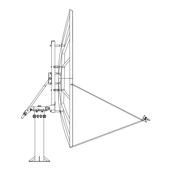
Page 36: Mount & Reflector Support Structure
4096-535 PRODELIN CORPORATION 3.8M C-BAND Rx/Tx ANTENNA SYSTEM MOUNT AND REFLECTOR SUPPORT STRUCTURE The mount and reflector support structure supplied with this antenna is of steel construction and has a galvanized finish with zinc w/ultraguard finish for hardware. If inspection shows any sign of structural failure, the mount members that are damaged should be repaired or replaced.
Need help?
Do you have a question about the 3.8M and is the answer not in the manual?
Questions and answers