
Related Manuals for AERMEC NLC


Summary of Contents for AERMEC NLC
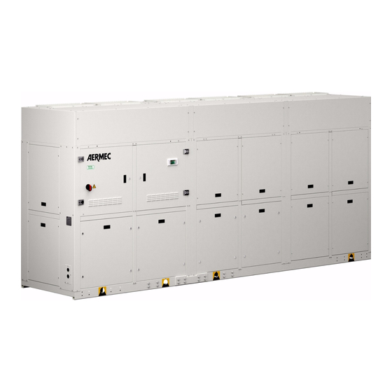
- Page 1 Installati on Manual Chiller Air/Water Indoor Installation 0750 A 1606.4037360_00...
- Page 2 Dear Customer, Thank you for choosing an AERMEC product. This product is the result of many years of experience and in-depth engineering research, and it is built using top quality materials and advanced technologies. We constantly monitor the quality level, and as a result AERMEC products are synonymous with Safety, Quality, and Reliability.
-
Page 3: Table Of Contents
Calibration of control and safety parameters ..................18 Routine maintenance ..........................19 Extraordinary maintenance ........................19 Troubleshooting ............................. 20 Lifting points and antivibrant position ....................21 Weight distribution and percentage on the supports / NLC A ............... 21 Distributors ............................. 22... -
Page 4: General Warnings For The Installer
GENERAL WARNINGS FOR THE INSTALLER REGULATIONS RESPECTED IN DESIGNING AND CONSTRUCTING The NLC AERMEC units are constructed according to the recognised THE UNIT technical standards and safety regulations. They have been designed for air conditioning and must be used for this purpose in accordance with Standards and Directives respected on their technical features. -
Page 5: Selection And Place Of Installation
31,50 in OPERATION OF THE NLC UNIT The chillers and the heat pumps of the NLC range are air-cooled machines suitable for installing indoors. For this reason the air that crosses the coil needs to be expelled from the utility room using suitable piping connected to the machine itself. -
Page 6: Max Static Useful Pressure Of The Fans
MAX STATIC USEFUL PRESSURE OF THE FANS ESP [Pa] Total air flow rate NLC A Total air flow rate Max ESP [Pa] Parameter fans max Volts [V] 0750 69000 40611,866 6,6/8,3 7,5/8,7 8,3/9,2 9,2/9,6 10,0/10,0 WARNING WARNING The weight of the piping must... -
Page 7: Main Hydraulic Circuits
50% of the nominal capacity Sulphate ions (SO4) < 50 ppm Sulphide ion (S) none Aermec will not be responsible for any Ammonium ions (NH4) none Silica (SiO2) < 30ppm damage to the heat exchanger if there is no water filter and flow switch NLC_A COD: 1606.4037360_00... -
Page 8: Electrical Wirings
INSTALLATIONS, following international regulations and the national regulations of the country in which the unit is installed, in compliance with The NLC units are fully wired in the factory and only require connection the legislative regulations in force at the moment of installation. -
Page 9: Electrical Data Table
ELECTRICAL DATA TABLE Power Supply: EARTH (PE) PHASE Total absorption Recommended cable sec. for Lmax = 50 m / 1 968,50 Inch Fuse Model Power No. Fans Sec. Phase Sec. PE No. cables Vers.* Compressors (recommended No. Phases per phase [mm²] [mm²] NLC0750... -
Page 10: Electronic Regulation (Pco 5 )
ELECTRONIC REGULATION (PCO5) ELECTRONIC CONTROL (pCO5) START-UP ANTI-FREEZE ALARM WATER FLOW ALARM CIRCULATING PUMP Reference parameters: If the water fl ow rate is not suffi cient, this safety stops the compressors and the pump Compressor BLOCK - OFF Turn the unit on (ON) BLOCCO - OFF Temperature >... - Page 11 • The address to enable board panel is 32 • The address to enable remote panel is 31 For more informati on, refer to the wiring diagrams in the selecti on program or site www.aermec.com NLC_A COD: 1606.4037360_00 EN - 11...
- Page 12 User Interface (PGD1) The unit control panel allow the quick setti ng and INTERFACE CONTROL KEYS display of the unit’s operati ng parameters. The board memorises all the default setti ngs and any modifi ca- Control Keys Control Keys ti ons. By installing the remote control panel PGD1 it is possible to remotely replicate all the functi ons and the setti ngs available on the unit.
- Page 13 Start-up procedure Aft er having powered up the unit the control board will select the system language. These screens are detailed any ti me through the appropriate screen contained carry out preliminary operati ons before being ready in the table below. in the Installer menu.
- Page 14 Menu structure and navigati on Both the functi ons to control the unit and the operati ng informati on The operati ng menus are arranged as in the following drawing: are displayed on the unit mounted control panel. All the functi ons and informati on are arranged in screens which in turn are grouped into menus.
- Page 15 User operating procedures To check or modify the operati ng parameters of the unit it is necessary to use the interface of the control panel on the unit. The basic operati ons that the user must be capable of, for the correct use of the unit, are: (1) Moving from one menu to the next.
-
Page 16: Loading The System
LOADING THE SYSTEM Before starting the loading, set the unit's master switch to OFF Check that the system discharge tap is closed Open all the drain valves of the system and of the related terminals Open the cut-off devices of the system. Start the filling by slowly opening the water system filling tap on the outside of the appliance. -
Page 17: Control And First Start-Up
Aermec Technical Service for Check the water flow rate, measuring the CHECK: the unit of this series, at the request of Aermec difference of pressure between the evaporator customers or legitimate owners and in ITALY inlet and outlet, and then calculate the flow THE MANUAL RESET HIGH PRESSURE only. -
Page 18: Calibration Of Control And Safety Parameters
CALIBRATION OF CONTROL AND SAFETY PARAMETERS °C °F 39,2 Cooling setting 64,4 44,6 Antifreeze intervention 39,2 37,4 37,4 Total differential NLC A 0750 Compressor magnetothermic switches calibrations MTC1 MTC1A MTC2 MTC2A Calibration fan thermomagnetic switch MTV1 MTV2 MTV2A High pressure safety valves intervention VSIC AP P.S.I. -
Page 19: Routine Maintenance
If they are poorly tightened, they produce abnormal noise and vibrations EXTRAORDINARY MAINTENANCE The NLC units are filled with R410A gas and inspected in the factory. Under normal conditions, no Technical Assistance Service operation is needed for checking the refrigerant gas. Over... -
Page 20: Troubleshooting
TROUBLESHOOTING IRREGULARITY CAUSE SOLUTION • Check for voltage • No electrical voltage • Check the safety systems upstream of the appliance • Master switch on OFF • Remote switch on OFF (if present) • Control panel on OFF • Set to ON •... -
Page 21: Lifting Points And Antivibrant Position
NLC 0750 A VERS.00 0750 A-E [01-08] 0750 A-E [00] [P1-P8] 0900 ° [01-08] 0900 ° [00] [P1-P8] WEIGHT DISTRIBUTION AND PERCENTAGE ON THE SUPPORTS / NLC A NLC 0750 A VERS.00 NLC0750A/E NLC0750A/E Vers. 00 / P1-P8 Vers. 01-08 0750 A-E [01-08] 0900 °... -
Page 22: Distributors
AERMEC SAS - AGENCE SILLON ALPIN - 7, Chemin des Roquevillard - 73160 Cognin - Tél. +33 04 85013570 - Fax +33 04 74090988 - jerome.dubouchet@aermec.fr AERMEC SAS - Ile de France - 80 Avenue du Général De Gaulle - 91170 Viry Chatillon - Tél. +33 1 60478348 - Fax +33 1 69436368 - gianni.delfabbro@aermec.fr DIMENA SARL - 88 Rue Du Moulineau - 33320 Eysines - Tél. - Page 23 UKRAINE AERMEK UKRAINE LLC, - Vorovskogo Str., build. 37/14 off. 304 - 01054 Kyiv 054 - Ph. +38 044 229 74 47 - Fax +38044 390 73-47 - apo@aermec.com.ua URUGUAY CLIMATIZACION INTEGRAL LTDA - Pedro Cosio 2064 - 11400 Montevideo - Tel. +598 26136565 - Fax +598 26136565 - pgiosa@climatizacion.com.uy UNITED STATES MITS AIR CONDITIONING Inc.
- Page 24 Tel. + 39 0442 633111 Fax +39 0442 93577 carta riciclata www.aermec.com recycled paper papier recyclé recycled Papier Aermec reserves the right to make all modification deemed necessary for improving the product at any time with any modification of technical data.
Need help?
Do you have a question about the NLC and is the answer not in the manual?
Questions and answers