Ergotron Neo-Flex Ceiling Mount Manual
Hide thumbs
Also See for Neo-Flex Ceiling Mount:
- Assembly instructions manual (22 pages) ,
- User manual (21 pages) ,
- Manual (19 pages)
Advertisement
Quick Links
www.ergotron.com
User's Guide - English
Guía del usuario - Español
Manuel de l'utilisateur - Français
Gebruikersgids - Nederlands
Benutzerhandbuch - Deutsch
Guida per l'utente - Italiano
Användarhandbok - svenska
ユーザーガイ ド : 日本語
用户指南 : 汉语
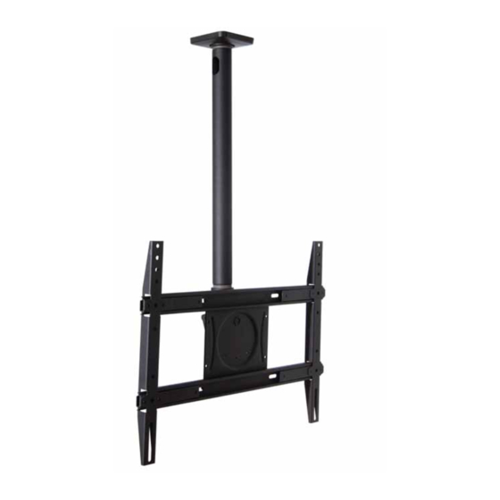
Max screen size: 65"
Max weight 125lbs – 56.7 kg
CAUTION: DO NOT EXCEED MAX-
IMUM LISTED WEIGHT CAPACITY.
SERIOUS INJURY OR PROPERTY
DAMAGE MAY OCCUR!
888-61-038-G-00 rev. B • 02/13
Neo-Flex® Ceiling Mount
Reduce.Reuse.Recycle
1 of 12
Advertisement

Related Manuals for Ergotron Neo-Flex Ceiling Mount


Summary of Contents for Ergotron Neo-Flex Ceiling Mount
- Page 1 Neo-Flex® Ceiling Mount www.ergotron.com User's Guide - English Guía del usuario - Español Manuel de l’utilisateur - Français Gebruikersgids - Nederlands Benutzerhandbuch - Deutsch Guida per l’utente - Italiano Användarhandbok - svenska ユーザーガイ ド : 日本語 用户指南 : 汉语 Max screen size: 65”...
-
Page 2: Hazard Symbols Review
Hazard Symbols Review Symbol Signal Word Level of Hazard These symbols alert users of a safety condition that A NOTE indicates important information that helps you demands attention. All users should be able to NOTE make better use of this product. recognize and understand the signifi cance of the fol- lowing Safety Hazards if encountered on the product A CAUTION indicates either potential damage to... -
Page 3: Tools Needed
Components Contents Part # Qty Description 1 Ceiling Plate 1 Celing Plate Cover 1 NPT pipe 1 NPT Pipe Set Scew 1 Single Tilt Head 1 Tilt Head Adjustment Screw 1 Tilt Pins 1 VESA Monitor Plate 4 M8 Hex Screw 1 Universal Monitor Adapter 4 M8Nylock Nut Screws / Hardware for Flat Panel (PN: 697-613) - Page 4 Monitor Plate Options 200mm ≤660mm ≤300mm OPTION B: Step 1 OPTION B: Step 2 888-61-038-G-00 rev. B • 02/13 4 of 12...
- Page 5 OPTION A: Step 1 Connect adapter to fl at panel OPTION B: Step 3 Connect adapter to fl at panel 888-61-038-G-00 rev. B • 02/13 5 of 12...
- Page 6 Find stud and mark edge and center locations Drill pilot hole 888-61-038-G-00 rev. B • 02/13 6 of 12...
- Page 7 Mount ceiling plate Assemble NOTE: Security Screw Must be installed for safe and proper installation 888-61-038-G-00 rev. B • 02/13 7 of 12...
-
Page 8: Attach Cover
Attach cover Assemble NOTE: Security Screw Must be installed for safe and proper installation 888-61-038-G-00 rev. B • 02/13 8 of 12... - Page 9 Hang with monitor attached NOTE: Security Screws Must be in- stalled for safe and proper installation 888-61-038-G-00 rev. B • 02/13 9 of 12...
- Page 10 Adjustment Step Adjust to Desired Location or Tilt 888-61-038-G-00 rev. B • 02/13 10 of 12...
- Page 11 Route Cables 888-61-038-G-00 rev. B • 02/13 11 of 12...
- Page 12 Set Your Workstation to Work For YOU! Confi gure su estación de trabajo para que trabaje para USTED. Ajustez votre station de travail en fonction de VOS besoins ! Richten Sie Ihren Arbeitsplatz so ein, dass er für SIE arbeitet! Stel uw werkstation zo in dat het voor U werkt! Approntare la stazione di lavoro nella posizione ergonomica ottimale.
Need help?
Do you have a question about the Neo-Flex Ceiling Mount and is the answer not in the manual?
Questions and answers