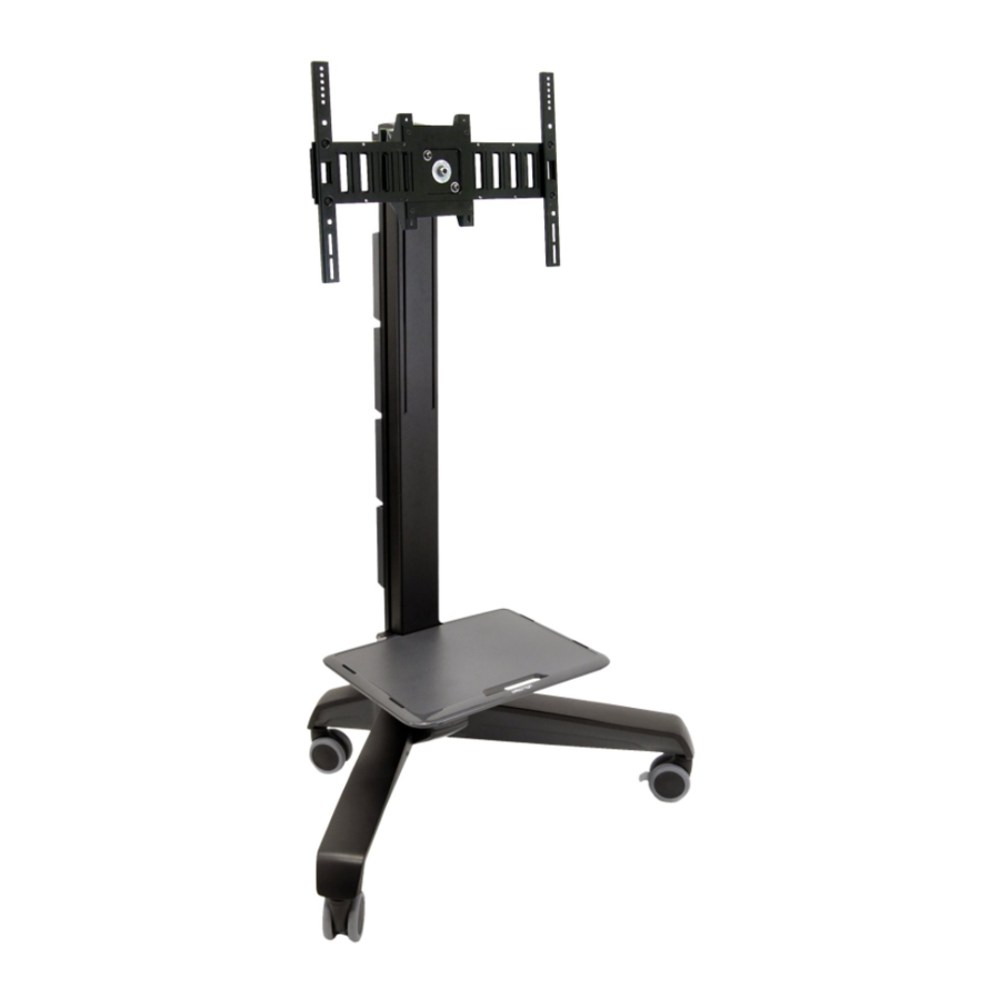
Ergotron Neo-Flex User Manual
Wall mount lift
Hide thumbs
Also See for Neo-Flex:
- Assembly instructions manual (22 pages) ,
- User manual (21 pages) ,
- Manual (19 pages)
Table of Contents
Advertisement
Quick Links
A
1x
1x
1
4x
1
Determine Ergonomic Mounting Height
(for wall mounted applications)
a
MEASURE -
The distance between the center line of
mounting holes and top of monitor screen.
b
CALCULATE -
• For Standing applications:
subtract 14" (359mm) and "x"
from 64" (1626mm) to fi nd
mounting height.
• For Sitting applications:
subtract 14" (359mm) and "x"
from 48.5" (1234mm) to fi nd
mounting height.
NOTE: this formula is designed to
provide ergonomic monitor viewing
for a wide range of users.
c
MARK - mounting height on wall. This
corresponds to the bottom of the wall bracket.
888-45-045-01 rev.C • 11/05
Thank you for purchasing this Ergotron Product!
Should you need assistance with assmebly, damaged
or missing parts, please call our Customer Care
Department at (800) 888-8458 (option 2).
B
2x
4x
1x
For optimum ergonomic viewing,
1x
1" below eye height of operator.
M5 x 12mm
Neo-Flex
C
1x
#10 x 2" wood screws
#10-24 x 5/8"
1/8"
set top of monitor screen
a
"Full-up" Position
b
c
User's Guide
™
Wall Mount Lift
USA 1-800-888-8458
Europe +31 20 312.29.39
D
64
(1626mm)
X
- 14
(359mm)
Mounting Height
48.5
(1234mm)
X
- 14
(359mm)
Mounting Height
4x
4x
1 of 6
Advertisement
Table of Contents

Subscribe to Our Youtube Channel
Summary of Contents for Ergotron Neo-Flex
- Page 1 Neo-Flex Wall Mount Lift USA 1-800-888-8458 Europe +31 20 312.29.39 Thank you for purchasing this Ergotron Product! Should you need assistance with assmebly, damaged or missing parts, please call our Customer Care Department at (800) 888-8458 (option 2). #10 x 2" wood screws #10-24 x 5/8"...
- Page 2 These fasteners are designed for mounting the Wall Bracket to wood studs only. Because surfaces vary widely and the ultimate mounting method is out of Ergotron’s control, it is imperative that you consult with appropriate engineering, architectural #10 x 2" wood screws...
- Page 3 Attach Stand to Monitor (75mm x 75mm or 100mm x 100mm) Start screws as far as possible by hand, then tighten with screwdriver. If your monitor has a 75mm (3") interface, you can gain better access by rotating the stand and angling the screwdriver as illustrated. •...
- Page 4 Attach Arm and Monitor to Wall Bracket CAUTION: Support arm and monitor until fasteners are completely installed. Failure to do so could result in equipment damage or personal injury. M5 x 12mm Range of Motion Lift - Up & Down Tilt - Back &...
- Page 5 Move monitor up and down through entire range of motion. If it does not stay in Lift Motion place at any point it will need adjustment - see below. Adjust so upward and down- ward moving forces are equal. Once this is achieved turn adjustment screw 2-4 turns clockwise to give slight upward bias to lift system.
- Page 6 © 2005 Ergotron, Inc. All rights reserved. Patents Pending and Patented U.S. & Foreign. Ergotron is a registered trademark of Ergotron, Inc. Reproduction of this material in whole or part for any purpose other than that authorized by Ergotron, Inc. is prohibited.


Need help?
Do you have a question about the Neo-Flex and is the answer not in the manual?
Questions and answers