Advertisement
Quick Links
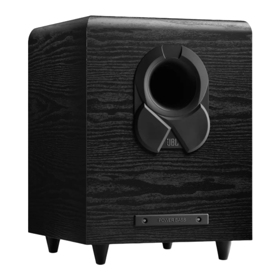
SP150 / 230
Active 10" Subwoofer.
Loft Series.
OWNER'S MANUAL
SPECIFICATIONS
PACKAGE GUIDE AND PARTS
EXPLODED VIEW
TROUBLESHOOTING FLOW CHART
Released EU2012
CONTENTS
PARTS LIST
2
SEMICONDUCTOR PINOUTS
7
PCB DRAWINGS
8
BLOCK DIAGRAMS
9
SCHEMATIC DIAGRAMS
11
Harman Consumer Group, Inc.
8500 Balboa Boulevard
Northridge, California 91329
Service Manual
Rev 0, 02/2012
12
18
41
47
49
Advertisement

Related Manuals for JBL SP150


Summary of Contents for JBL SP150
- Page 1 Service Manual SP150 / 230 Active 10” Subwoofer. Loft Series. CONTENTS PARTS LIST OWNER’S MANUAL SEMICONDUCTOR PINOUTS SPECIFICATIONS PCB DRAWINGS PACKAGE GUIDE AND PARTS BLOCK DIAGRAMS EXPLODED VIEW SCHEMATIC DIAGRAMS TROUBLESHOOTING FLOW CHART Released EU2012 Harman Consumer Group, Inc. Rev 0, 02/2012...
- Page 2 Your new JBL ® SP-150 150-watt powered subwoofer incorporates We’re confident that this JBL subwoofer will provide every note a 10" (250mm) down-firing cone transducer and a built-in high- of enjoyment that you expect – and that when you think about...
- Page 3 150P / 230V Service Manual iMPorTanT saFeTY insTruCTions 1. Read these instructions. The lightning flash with arrowhead symbol, within an equilateral 2. Keep these instructions. triangle, is intended to alert the user to the presence of uninsulated 3. Heed all warnings. “dangerous voltage”...
- Page 4 Crossover control, the higher in frequency the subwoofer will oper- ate and the more its bass will “overlap” that of the satellite speakers. This AC Fuse holder: The SP150 is factory-equipped with a 2A/250V AC fuse. adjustment helps achieve a smooth transition of bass frequencies between...
- Page 5 Place the subwoofer in that location. ConneCTing The suBwooFer TO A RECEIVER OR PREAMP/PROCESSOR WITH A LINE-LEVEL SUbWOOFER OUTPUT Receiver or Amplifier RCA Audio Cable (not supplied) SP150 Subwoofer Page 4 of 50...
- Page 6 150P / 230V Service Manual TO A RECEIVER WITHOUT A LINE-LEVEL SUbWOOFER OUTPUT Front Left Front Right Speaker Speaker Speaker Wire (not supplied) Speaker Wire (not supplied) SP150 Subwoofer FRONT SURROUND SPEAKERS SPEAKERS CENTER SPEAKER Receiver or Amplifier www.jbl.com Page 5 of 50...
- Page 7 © 2012 HARMAN International Industries, Incorporated. All rights reserved. JBL is a trademark of HARMAN International Industries, Incorporated, registered in the United States and/or other countries. Features, specifications and appearance are subject to change without notice. Part No. 950-0457-001, Rev.: A...
- Page 8 150P / 230V Service Manual This place with CUT is to fit front of subwoofer PE bag EPE bag styrofoam top cover styrofoam bottom cover manual packing desiccant, 25g/bag illustration carton sealing tape Page 7 of 50...
- Page 9 150P / 230V Service Manual P/N. P/N. Name Name Q'ty Q'ty SP150/230 port tube 29040004 paper tube self-tapping screw lighted badge tube head cabinet woofer self-tapping foot screw exploded view Page 8 of 50...
- Page 10 150P / 230V Service Manual 5 -1 1 3- 1 5 -4 1 3- 2 13-4 13-5 13-6 13- 3 13-7 13- 8 Part No. 料号 Part Name 名称 Q'ty 用量 序 号 Part No. 料号 Part Name 名称 Q'ty 用量...
- Page 11 150P / 230V Service Manual SP150/230 Trouble Shooting Flow Chart no or lower POWER ±VCC(±2V) Check DC ① check U4.Q1.U1.BD3.T1 voltages no or lower ±19V(±1V) no or lower check R82.R83 ±12V(±1V) Test DC ② ② voltages no or lower check Q8.Q21.Q22.Q23.R80.R81 ±10V(±1V)...
- Page 12 150P / 230V Service Manual JBL SP150/230 powered subwoofer spare parts list. AMP part no. BB000014 Product:Sub Amplifier Part No. Part Name Specs Q'ty Designation Unite K0100354 POWERAMP pcb RX150N PCB ASSY. MS100- 10010037 PCB PWR&,V.A2,150*85*1.6mm,green oil, semi-glass fiber 1/8W 220Ω ±1% 0805 11170017 SMT Res.
- Page 13 150P / 230V Service Manual 60020002 photocoupler PC817 DIP4 2W 0.1Ω 5% Vertical, non-inductive 11150017 wirewound Res. L=4mm 50010046 ceramic Cap. 471/250V ±5% SL P=5mm L=4mm C39.40 50010071 ceramic Cap. 472/1KV ±20% blue P=5mm L=4mm 50030030 MOF 224/100V ±5% P=5mm L=4mm C54.57 50030031 MOF 684/100V ±5%...
- Page 14 40360042 PIN header 9P P=2.54mm 180 degree CON1A 40360028 PIN header 9P P=2.54mm 90 degree L=12mm CON3B K0100356 filter PCB(preamp) SP150N JBL PCB ASSY. RX-PRE V.A1 132*58*1.6mm green oil 10010051 PCB 94V0,single side 1/8W 0Ω ±1% 0805 11170001 SMT Res. R16.23.62.R00 1/8W 100Ω...
- Page 15 150P / 230V Service Manual 11170339 SMT Res. 1/8W 5.36K ±1% 0805 11170426 SMT Res. 1/8W 6.65K ±1% 0805 11170073 SMT Res. 1/8W 9.1K ±1% 0805 R56.58.60 11170074 SMT Res. 1/8W 10K ±1% 0805 R9-10.12.27.79-80.83 11170081 SMT Res. 1/8W 15K ±1% 0805 R2.77 11170086 SMT Res.
- Page 16 150P / 230V Service Manual 22uF/50V,105℃,+/-20%,Φ5*11mm 17010032 E.C. C22.34.36.39 L=4mm 47uF/25V,105℃,+/-20%,Φ5*11mm 17010040 E.C. C3.35.10.11 L=4mm 100uF/25V,105℃,±20%,Φ6.3*11mmL=4 17010053 E.C. C1.2.9 mm black 40370002 connector 2532-02-180 degree 40370015 connector 2532-04-180 degree MS-102-C4L,no thread &MTS-102-C4 12050014 toggle switch S1.2 no thread 15010026 potentiometer R1209G12A3-A50K VR1 with nut and wather 15010027 potentiometer...
- Page 17 150P / 230V Service Manual fix amp panel to spacer on poweramp pcb, bracket on 70010031 M.Screw M3*8mm , black preamp pcb, amp panel to heatsink M3*18mm , black fix D5.6 70010051 M.Screw M.Screw with flat M3*12mm , black fix IC 70010043 washer Φ3.2*6*0.7mm , black...
- Page 18 150P / 230V Service Manual UNISONIC TECHNOLOGIES CO., LTD 2SA1015 PNP SILICON TRANSISTOR LOW FREQUENCY PNP AMPLIFIER TRANSISTOR FEATURES * Collector-Emitter Voltage: BV =-50V * Collector Current up to 150mA * High h Linearity * Complement to UTC 2SC1815 Lead-free: 2SA1015L Halogen-free: 2SA1015G ORDERING INFORMATION...
- Page 19 150P / 230V Service Manual 2SA1015 PNP SILICON TRANSISTOR ABSOLUTE MAXIMUM RATING (Ta=25°C, unless otherwise specified ) PARAMETER SYMBOL RATINGS UNIT Collector-Base Voltage Collector-Emitter Voltage Emitter-Base Voltage Collector Current -150 Base Current Collector Dissipation Junction Temperature °C Storage Temperature -55 ~ +125 °C Note: Absolute maximum ratings are those values beyond which the device could be permanently damaged.
- Page 20 150P / 230V Service Manual 2SJ108 TOSHIBA Field Effect Transistor Silicon P Channel Junction Type 2SJ108 Low Noise Audio Amplifier Applications Unit: mm · Recommended for first stages of EQ amplifiers and MC head amplifiers. · High |Y |: |Y | = 22 mS (typ.) = −10 V, V = 0, I...
- Page 21 150P / 230V Service Manual UNISONIC TECHNOLOGIES CO., LTD 2SC1815 NPN SILICON TRANSISTOR AUDIO FREQUENCY AMPLIFIER HIGH FREQUENCY OSC NPN TRANSISTOR FEATURES * Collector-Emitter voltage: =50V * Collector current up to 150mA * High h linearity * Complimentary to UTC 2SA1015 ORDERING INFORMATION Ordering Number Pin Assignment...
- Page 22 150P / 230V Service Manual 2SC1815 NPN SILICON TRANSISTOR ABSOLUTE MAXIMUM RATING (Ta=25℃,unless otherwise specified ) PARAMETER SYMBOL RATINGS UNIT Collector-Base Voltage Collector-emitter voltage Emitter-Base Voltage Collector Current Base Current Power Dissipation(Ta=25℃) ℃ Junction Temperature +125 ℃ Storage Temperature -55 ~ +125 Note Absolute maximum ratings are those values beyond which the device could be permanently damaged.
- Page 23 150P / 230V Service Manual Page 22 of 50...
- Page 24 150P / 230V Service Manual MOTOROLA Order this document SEMICONDUCTOR TECHNICAL DATA by MMBT3904LT1/D General Purpose Transistor MMBT3904LT1 NPN Silicon COLLECTOR Motorola Preferred Device BASE EMITTER MAXIMUM RATINGS Rating Symbol Value Unit CASE 318 – 08, STYLE 6 Collector – Emitter Voltage V CEO SOT–...
- Page 25 150P / 230V Service Manual MMBT3904LT1 PACKAGE DIMENSIONS NOTES: 1. DIMENSIONING AND TOLERANCING PER ANSI Y14.5M, 1982. 2. CONTROLLING DIMENSION: INCH. 3. MAXIMUM LEAD THICKNESS INCLUDES LEAD FINISH THICKNESS. MINIMUM LEAD THICKNESS IS THE MINIMUM THICKNESS OF BASE MATERIAL. INCHES MILLIMETERS 0.1102 0.1197...
- Page 26 150P / 230V Service Manual MOTOROLA Order this document SEMICONDUCTOR TECHNICAL DATA by MMBT3906LT1/D General Purpose Transistor MMBT3906LT1 COLLECTOR PNP Silicon Motorola Preferred Device BASE EMITTER MAXIMUM RATINGS Rating Symbol Value Unit Collector – Emitter Voltage V CEO –40 CASE 318 – 08, STYLE 6 Collector –...
- Page 27 150P / 230V Service Manual MMBT3906LT1 PACKAGE DIMENSIONS NOTES: 1. DIMENSIONING AND TOLERANCING PER ANSI Y14.5M, 1982. 2. CONTROLLING DIMENSION: INCH. 3. MAXIMUM LEAD THICKNESS INCLUDES LEAD FINISH THICKNESS. MINIMUM LEAD THICKNESS IS THE MINIMUM THICKNESS OF BASE MATERIAL. INCHES MILLIMETERS 0.1102 0.1197...
- Page 28 150P / 230V Service Manual Page 27 of 50...
- Page 29 150P / 230V Service Manual Page 28 of 50...
- Page 30 150P / 230V Service Manual TDA8920C 2 × 110 W class-D power amplifier Rev. 01 — 29 September 2008 Preliminary data sheet 1. General description The TDA8920C is a high-efficiency class-D audio power amplifier. The typical output power is 2 × 110 W with a speaker load impedance of 4 Ω. The TDA8920C is available in both HSOP24 and DBS23P power packages.
- Page 31 150P / 230V Service Manual TDA8920C NXP Semiconductors 2 × 110 W class-D power amplifier 4. Quick reference data Table 1. Quick reference data Symbol Parameter Conditions Unit = ±30 V General, V ±12.5 ±30 ±32.5 V supply voltage Operating mode overvoltage protection Non-Operating mode;...
- Page 32 150P / 230V Service Manual TDA8920C NXP Semiconductors 2 × 110 W class-D power amplifier 7. Pinning information 7.1 Pinning IN1P IN1M n.c. n.c. n.c. PROT VDDP1 BOOT1 OUT1 VSSP1 VSSD VSSA TDA8920CJ STABI VDDP2 SGND VSSP2 BOOT2 VDDA OUT2 OUT2 IN2M BOOT2...
- Page 33 150P / 230V Service Manual TDA8920C NXP Semiconductors 2 × 110 W class-D power amplifier 7.2 Pin description Table 3. Pin description Symbol Description TDA8920CTH TDA8920CJ VSSA negative analog supply voltage SGND signal ground VDDA positive analog supply voltage IN2M channel 2 negative audio input IN2P channel 2 positive audio input...
- Page 34 150P / 230V Service Manual TDA8920C NXP Semiconductors 2 × 110 W class-D power amplifier 14. Package outline DBS23P: plastic DIL-bent-SIL power package; 23 leads (straight lead length 3.2 mm) SOT411-1 non-concave view B: mounting base side β 10 mm scale DIMENSIONS (mm are the original dimensions) β...
- Page 35 150P / 230V Service Manual TDA8920C NXP Semiconductors 2 × 110 W class-D power amplifier HSOP24: plastic, heatsink small outline package; 24 leads; low stand-off height SOT566-3 pin 1 index (A 3 ) θ detail X 10 mm scale DIMENSIONS (mm are the original dimensions) θ...
- Page 36 150P / 230V Service Manual PROGRAMMABLE PRECISION SHUNT REGULATOR TL431/A /C TO-92 PKG (TOP VIEW) 3. CATHODE PROGRAMMABLE PRECISION REFERENCES 2. ANODE The TL431 is three-terminal adjustable shunt regulator with specified termal stability. 1. REF The output voltage may be set to any value between (Approx.
- Page 37 150P / 230V Service Manual OB2269C Frequency Shuffling Current Mode PWM Controller Package Dissipation Rating GENERAL INFORMATION Package RθJA (°C/W) Pin Configuration DIP8 The OB2269C is offered in DIP and SOP packages SOP8 shown as below. Absolute Maximum Ratings Parameter Value VDD/VIN DC Supply 30 V...
- Page 38 150P / 230V Service Manual OB2269C Frequency Shuffling Current Mode PWM Controller Marking Information TERMINAL ASSIGNMENTS Pin Num Pin Name I/O Description Ground Feedback input pin. PWM duty cycle is determined by voltage level into this pin and current-sense signal level at Pin 6. Connected through a large value resistor to rectified line input for Startup IC supply and line voltage sensing.
- Page 39 150P / 230V Service Manual OB2269C Frequency Shuffling Current Mode PWM Controller PACKAGE MECHANICAL DATA 8-Pin Plastic DIP ©On-Bright Electronics Confidential - 11 - OB_DOC_DS_69CC1 Page 38 of 50...
- Page 40 150P / 230V Service Manual OB2269C Frequency Shuffling Current Mode PWM Controller 8-Pin Plastic SOP ©On-Bright Electronics Confidential - 12 - OB_DOC_DS_69CC1 Page 39 of 50...
- Page 41 150P / 230V Service Manual Page 40 of 50...
- Page 42 150P / 230V Service Manual Page 41 of 50...
- Page 43 150P / 230V Service Manual Page 42 of 50...
- Page 44 150P / 230V Service Manual Page 43 of 50...
- Page 45 150P / 230V Service Manual Page 44 of 50...
- Page 46 150P / 230V Service Manual Page 45 of 50...
- Page 47 150P / 230V Service Manual Page 46 of 50...
- Page 48 150P / 230V Service Manual Page 47 of 50...
- Page 49 220K TDA8920CTH 104/cc face plate 2.2M -10V PHASE 470K 0-180 47/25 LIMITER -15V 102/CC COMPANY TRISTAR ELECTRONIC CO.,LTD -10V SP150 -PRE TITLE-SCH TITLE-PCB RX-PRE VA1 DRAWN DATE DATE APPROVED DATE CHCKED J108 12.01.13 FILE NO. SIZE SHEET 01 OF 01 TRISTAR R&D JZHANG...
- Page 50 VSSA VSSP -VCC D3.5*L9.0 TO-PREAMP STANDBY CON2 CON-ECI2532-07 6.8k COMPANY: TRISTAR ELECTRONIC CO.,LTD. -19V TITLE: TITLE: MS100 -POWERAMP ( standby<1W ) SP150 2012-2-6 -12V -10V DRAWN: CHECKED: DATED: APPROVED: DATED: 2SA1015 DATED: 1.54K/1206 12.02.05 PT-X-XXXXX-XX 1 2 / DWG NO:...
- Page 51 222/400V Y1 PC817 EGND HGND STANDBY HGND EGND COMPANY: TRISTAR ELECTRONIC CO.,LTD. EGND TITLE: TITLE: 2012-2-6 MS100-POWER SUPPLY ( standby<1W ) SP150 DRAWN: CHECKED: DATED: APPROVED: DATED: DATED: 12.02.05 PT-X-XXXXX-XX DWG NO: SIZE: SIZE-A3 REV:A2 SHEET: 2 OF2 Page 50 of 50...
Need help?
Do you have a question about the SP150 and is the answer not in the manual?
Questions and answers