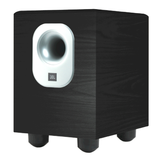
JBL Balboa SUB10 Service Manual
Balboa series
Hide thumbs
Also See for Balboa SUB10:
- Service manual (26 pages) ,
- Owner's manual (9 pages) ,
- Owner's manual (9 pages)
Advertisement
Table of Contents
- 1 Table of Contents
- 2 Basic Specifications
- 3 Packing
- 4 Detailed Specifications
- 5 Controls and Connections
- 6 Operation
- 7 Test Set-Up and Procedure
- 8 Exploded View/Parts List
- 9 Amplifier Block Diagram
- 10 Detailed Troubleshooting
- 11 Electrical Parts List
- 12 Drawings
- 13 IC/Transistor Pinouts
- 14 Schematics
- Download this manual
See also:
Owner's Manual
Advertisement
Table of Contents

Summary of Contents for JBL Balboa SUB10
- Page 1 Balboa Series ™ SUB10 Powered Subwoofer Service Manual JBL Consumer Products 250 Crossways Park Dr. Woodbury, New York 11797 Rev0 10/2006...
-
Page 2: Table Of Contents
Dimensions (H x W x D): Weight: JBL continually strives to update and improve existing products, as well as create new ones. The specifications and details in this and related JBL publications are therefore subject to change without notice. * The Peak Dynamic Power is measured by recording the highest center-to-peak voltage measured across the output of a resistive load equal to minimum impedance of the transducer, using a 50Hz sine wave burst, 3 cycles on, 17 cycles off. -
Page 3: Packing
BALBOA series SUB10... -
Page 4: Detailed Specifications
4 first consecutive peaks Highest RMS of the first 4 consecutive peaks Measured at amplifier board speaker out terminals, Output power 90 Watts THD < 0.1 % Single input driven 1 input driven... - Page 5 @ 230V-50 Hz (Nom.line voltage) Functional Direct short at output Functional @1/8 max unclipped Power Functional DC present at Speaker Out leads Amps Type-T or Slo Blo Amps Type-T or Slo Blo Notes AC Line cycled from OFF to ON...
-
Page 6: Controls And Connections
BALBOA series SUB10 CONTROLS AND CONNECTIONS Rear Panel ® A Harman International Company ¡ ™ £ ¢ ∞ § ¶ FUSE 120V T 2.5A L 250V 60HZ TYPE 200 Watts Subwoofer-Level Control Crossover Adjustment Phase Switch LFE Input Line-Level Inputs Power Indicator LED Power Switch... - Page 7 BALBOA series SUB10 SUBWOOFER CONNECTIONS Choose the Subwoofer Connection That Is Most Suitable for Your Receiver/Processor If you have a Dolby ® Digital or DTS ® receiver/processor with a low-frequency-effects (LFE) or subwoofer output: SUBWOOFER OR LFE OUTPUT If your receiver/processor does not contain a Dolby Digital or DTS processor but has a subwoofer output: NOTE: Some receivers have one subwoofer output.
-
Page 8: Operation
Phase Control The Phase Switch £ determines whether the subwoofer speaker’s piston-like action moves in and out with the main speakers (0˚), or opposite the main speakers (180˚). Proper phase adjustment depends on several variables such as room size, subwoofer placement and listener position. -
Page 9: Test Set-Up And Procedure
3. Connect a pair of speaker cables to driver terminals. Cables should be connected to an integrated amplifier fed by a signal generator. Turn on generator and adjust so that speaker level output is 5.0V. 4. Sweep generator from 20Hz to 1kHz. Listen to driver for any rubbing, buzzing, or other unusual noises. -
Page 10: Exploded View/Parts List
BALBOA series SUB10 EXPLODED VIEW... -
Page 11: Amplifier Block Diagram
BALBOA series SUB10... - Page 12 BALBOA series SUB10...
-
Page 13: Detailed Troubleshooting
LED light green Check U202 pin14 signal Check limiter board C304 Test R121,R122 signal Check RY101,D102,Q113,Q114 etc Check U101,Q115,Q116,R138 etc Check P102 signal BALBOA SUB10 (UL) AMP Troubleshooting Flow Chart Check Fuse,Transformer, D110, etc Check Q117,118,119,D109 etc LED red Check,Q206,Q207,U203 etc... -
Page 14: Electrical Parts List
BALBOA series SUB10 Balboa SUB10 (120v) Electrical Parts List Part Number Description POWER/MAIN PCB Resistors 110-14472j26-e Resistor 4.7K 1/4W ±5% CF 26mm (RoHS) 110-14681j26-e Resistor 680Ω 1/4W ±5% CF 26mm (RoHS) 110-16101j26-e Resistor 100Ω 1/6W ±5% CF 26mm (RoHS) 110-16102j26-e Resistor 1K 1/6W ±5% CF 26mm (RoHS) - Page 15 BALBOA series SUB10 Part Number Description POWER/MAIN PCB 190-06m4558d-e I.C. OPA 4558D (RoHS) DUAL OP-AMP 192-021tip35c-e transistor TIP35C (RoHS) NPN 192-022tip36c-e transistor TIP36C (RoHS) PNP 192-201d882y-e *transistor KSD882Y (RoHS) NPN 192-202b772y-e *transistor KSB772Y (RoHS) PNP 192-027c1815gr-e transistor 2SC1815GR TOSHIBA(RoHS) NPN 192-991d669a-e transistorHI-SINCERITY HSD669A(RoHS) NPN 192-992b649t-e...
- Page 16 BALBOA series SUB10 Part Number Description PREAMP PCB 129-a154j633-e metalized cap. 0.15U 63V ±5% MSC (RoHS) 129-a274j633-e metalized cap. 0.27uf 63V ±5% (RoHS) 129-a473j633-e metalized cap. 0.047U 63V ±5% MSC (RoHS) 129-a474j633-e metalized cap. 0.47U 63V ±5% MSC (RoHS) 129-a563j633-e metalized cap.
- Page 17 BALBOA series SUB10 Part Number Description LIMITER PCB Miscellaneous 162-50289001-e CABLE ASS'Y wire 280mm AWG26 162-80098201-e wire 90mm 28AWG (RoHS) 175-9f40hr2-e wire connector&base 40PIN PITCH=2.54mm HR2*40 (RoHS) 104-tlx1100av-e PCB 4connectors (RoHS) MISCELLANEOUS/MECHANICAL 123-14j70d-e Ferrite Core U-16.3*8.2*13(J70)+CASE (RoHS) 130-3f472md00-e disc capacitor 4700P 400V ± 20% (RoHS) 150-e8604107-e Power transformer EI-86 60Hz 120V TT0869906580 152-u602015-e...
-
Page 18: Drawings
BALBOA series SUB10... - Page 19 BALBOA series SUB10...
- Page 20 BALBOA series SUB10...
- Page 21 BALBOA series SUB10...
- Page 22 BALBOA series SUB10...
- Page 23 BALBOA series SUB10...
-
Page 24: Ic/Transistor Pinouts
BALBOA series SUB10... -
Page 25: Schematics
R258 4.7K R259 R266 R264 C234 R262 100K 1.2K 100uF C233 100uF LED1 FILENAME: PRE-AMP MODEL NO. BALBOA SUB10 BK CUSTOMER: JBL DATE: 2006-09-20 C246 C244 C243 C251 +15V 10uF 10uF 0.1uF/C 0.1uF/C +15v U203 4558 U202... - Page 26 BALBOA series SUB10...
- Page 27 BALBOA series SUB10...


Need help?
Do you have a question about the Balboa SUB10 and is the answer not in the manual?
Questions and answers