
Related Manuals for JBL Sub 6


Summary of Contents for JBL Sub 6
- Page 1 Sub 6/10 This Service Manual covers the Sub6 and Sub10 models SERVICE MANUAL SERVICE MANUAL JBL Consumer Products 250 Crossways Park Dr. Woodbury, New York 11797 RevB 7/2003...
-
Page 2: Table Of Contents
JBL continually strives to improve its products. New materials, production methods and design refinements are introduced into existing models without notice as a routine expression of our design philosophy. For this reason, Sub 6/10 may differ in some respect from their published specifications and descriptions, but will always equal or exceed the original specifications unless... -
Page 3: Sub6/10 Disassembly Procedures
Powered Subwoofer SUB 6/10 SUB6/10 DISASSEMBLY PROCEDURE Unplug all external connecting cables. Removal of power transformer: Remove the ½” plated screws holding the small oval cover inside the Place the subwoofer on a padded surface so that the input cup; remove cover. -
Page 4: Sub6/10 Controls
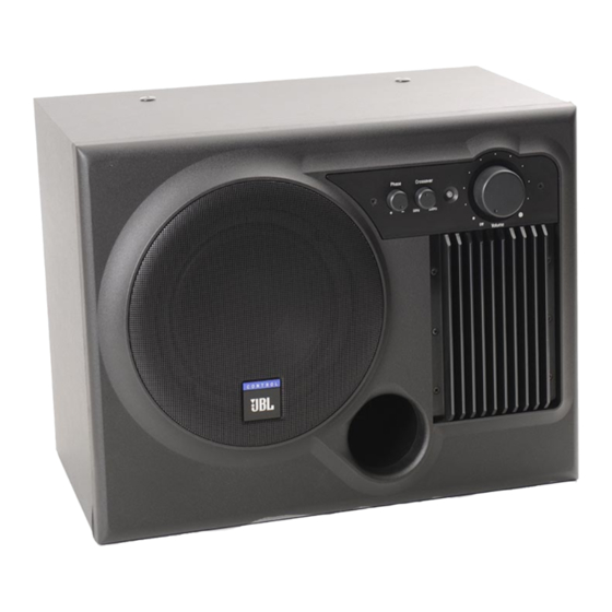
Powered Subwoofer SUB 6/10 SUB6/10 CONTROLS 1. Volume/Power - This knob controls the volume as well satellite speakers are attached to the OUTPUT as the power status of the subwoofer. The Sub6/10 terminals, they are driven the full range of subwoofers incorporate an AutoTurn-On/Off Circuit. -
Page 5: Test Procedure
Powered Subwoofer SUB 6/10 SUB6/10 POWERED SUB WOOFER TEST SETUP TEST PROCEDURE Equipment Needed: Turn on generator and adjust so that speaker level output is 1.2V, 50 Hz. Function generator/signal generator/sweep generator Turn volume knob full clockwise to turn unit ON for maximum output. -
Page 7: Sub 6/10 Exploded Assembly View
Powered Subwoofer SUB 6/10 SUB 6/10 EXPLODED ASSEMBLY VIEW (refer to pages 7 and 10) -
Page 10: Sub6 Part Lists
Control Sub 6/10 SUB6 PART LISTS SUB 6-MECHANICAL PARTS LIST F1618 SCREW FOR HEATSINK #5.8 x 16mm L Ref No. Part No. Description Qty. F1226 SCREW FOR PORT TUBE 7 xM4xL12 EVM0006-001 WOOD BOX F2507 SCREW FOR BAFFLE J1333B FRONT CAB (BLACK) - Page 11 Control Sub 6/10 SUB6 PART LISTS (continued) Ref. No. Part No. Description Qty. Ref. No. Part No. Description Qty. R156 QAF0650-563 RESISTOR 56K OHM 1/6W 5% CF Resistors R169 QAF0650-333 RESISTOR 33K OHM 1/6W 5% CF R101, 107, QAF0650-332 RESISTOR 3.3K OHM 1/6W 5% CF...
- Page 12 SIL PAD 3000+-500LBS BERQUIST 400 20x25mm CN306 CCN3951-002 CONNECTOR 2 PIN LEOCO 3951 P=3.96 POST BASE TOP GAL0040-001 HEAT SINK JBL CM-6 60W BLACK CN901 CCN3941-003 CONNECTOR 3 PIN PITCH=3.96mm 1 GSE0073-002 PCB BKT JBL CM-10/CM-6 POST BASE TOP GSI0001-001 SI RUBBER 13x18x0.3t mm...
-
Page 13: Sub10 Part Lists
Control Sub 6/10 SUB10 PART LISTS SUB10 MECHANICAL PART LIST F1618 SCREW FOR PANEL/HSINK 6.5 xM3xL16 Ref No. Part No. Description Qty. F1226 SCREW FOR PORT TUBE 7 xM4xL12 EVM0005-001 WOOD BOX F2507 SCREW FOR BAFFLE 8 xM4xL25 J1334B FRONT CAB (BLACK) - Page 14 Control Sub 6/10 SUB10 PART LISTS (continued) Ref No. Part No. Description Qty. Ref No. Part No. Description Qty. C906-907 PRD3545-102 COND DISC 1000pF 50V 10% Y5P R152-153 QHE5050-228 0.22 OHM 5W 5% CEMENT FIXED RES R156 QAF0650-563 56K OHM 1/6W 5% CF...
- Page 15 PAD 3000 +-500 LBS P=3.96 POST BASE TOP BERQUIST 400 20x25mm CN901 CCN3941-003 CONNECTOR 3 PIN PITCH= GAL0039-001 HEAT SINK JBL CM-10 100W BLK 3.96 mm POST BASE TOP GSE0073-002 PCB JBL CM-10/CM-6 CN902A CCN3951-003 CONNECTOR 3 PIN LEOCO 3951 P=3.96 POST BASE TOP...
-
Page 16: Sub 6/10 Packaging
SUB 6/10 PACKAGING VIEW... -
Page 17: Printed Circuit Boards
Control Sub 6/10 PRINTED CIRCUIT BOARDS #1... - Page 18 Control Sub 6/10 PRINTED CIRCUIT BOARDS #2...
- Page 19 Control Sub 6/10 PRINTED CIRCUIT BOARDS #3...
-
Page 20: Integrated Circuit Diagrams
INTEGRATED CIRCUIT DIAGRAM... - Page 21 INTEGRATED CIRCUIT DIAGRAM...
-
Page 23: Sub6 Wiring Diagram
Control Sub 6/10 SUB6 WIRING DIAGRAM... -
Page 24: Sub10 Wiring Diagram
SUB10 WIRING DIAGRAM... -
Page 25: Sub 6/10 Schematic Diagram
SUB 6/10 SCHEMATIC DIAGRAM...
Need help?
Do you have a question about the Sub 6 and is the answer not in the manual?
Questions and answers