Table of Contents
Advertisement
Advertisement
Table of Contents

Related Manuals for ATECH CRATER-06 A


Summary of Contents for ATECH CRATER-06 A
- Page 1 CRATER-06 A AUTOMATIC UPCUT MITER SAW USER’S MANUAL...
-
Page 2: Table Of Contents
CONTENTS 1. General Information 1.1. Introduction 1.2. Distributor 2. Definition of the Machine and its Use 2.1. Definition of the Machine 2.2. Technical Features 2.3. Cutting Diagram 2.4. Overall Dimensions 2.5. Parts List and Technical Drawings 2.6. Electric and Pneumatic Control Panel 2.7. -
Page 3: General Information
Ph.: +1-240-505-1967 * Fax: +1-301-560-6627 info@ATechMachinery.com *In case of any technical problem please contact your nearest ATECH dealer or ATECH head office through the above mentioned phone, fax numbers or e-mail address. *Technical labels with the model description of the machine are attached onto the front side of each machine. -
Page 4: Technical Features
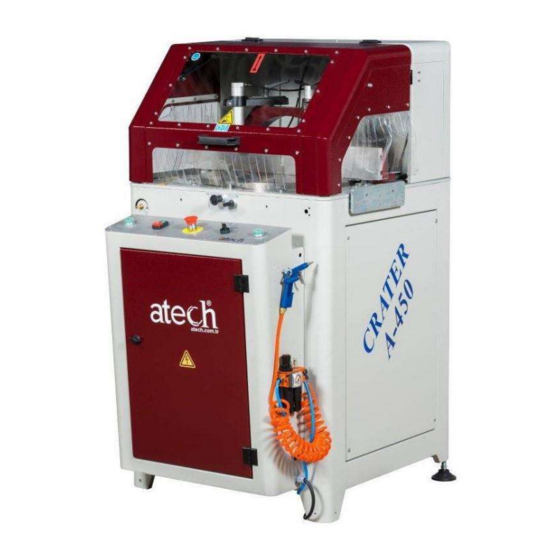
Figure 1 : Adjustment of Saw Blade Rising Speed Top Guard Control Panel Electric and Pneumatic Panel The saw blade will not rise for safety reasons unless the top guard is fully closed. 2.2. TECHNICAL FEATURES 6-8 Bar D=450 mm (18”) 80x96x137 cm 225 kg 2.2 KW / 3 HP... -
Page 5: Cutting Diagram
2.3. CUTTING DIAGRAM 2.4. OVERALL DIMENSIONS 2.5. PARTS LIST AND TECHNICAL DRAWINGS... - Page 6 PART NO PART NAME CR-450_ MOTOR_GROUP_BED 6205_ZZ_BEARING CR-450_MOTOR_TENSION_LOG CR-450_MOTOR_TENSION_SHEET_METAL CR-450_BEARING_COVER CR-450_SAW_SHAFT CR-450_SAW_SHAFT_PIPE PJ_BELT_MOTOR_PULLEY (Q52x56x10KNL) PJ-483_BELT MOTOR_2.2KW_B14_3000RPM LME-30-UU SAW COUPLING WASHER 30-32 mm SAW BLADE Ø450 (18”) REAR CLEVIS SPECIAL WASHER CR-450_SAW_FLANGE CR-450_MOTOR_PULLEY_WASHER CR-450_SAW_SHAFT_NUT CR-450_MOTOR_TENSION_BOLT_PRESSING_WASHER CR-450_SAW_SAFETY A_H.B_M6x20 A_H.B_M8x20...
-
Page 7: Electric And Pneumatic Control Panel
INBUS_M6x50 INBUS_M8x35 INBUS_M10x30 SETSCREW_M4x2,5 NARROW_STRAIGHT_WASHER _M8 A.A_M6x40 INBUS_M6x16 NUT_M6 2.6. ELECTRIC AND PNEUMATIC CONTROL PANEL Motor Emergency Stop Button Cutting Button Cutting Button Motor Start-Stop Button Release Pin-Setting Bolt for Fixing of Air Gun Locked Angles Intermediate Angles The operator panel is located in front of the saw table. In case of any repair or maintenance the power has to be cut off prior to acces of this electric panel. -
Page 8: Pneumatic Circuit Scheme
2.7. PNEUMATIC CIRCUIT SCHEME... - Page 9 2.8 ELECTRIC POWER SCHEME...
-
Page 10: Safety
SAFETY... -
Page 11: Safety Information
3.1. SAFETY INFORMATION The symbols shown hereunder are necessary to be read with special attention. Not reading or observing of them may cause damage to the equipment or personal injury. IMPORTANT The IMPORTANT symbol above is one telling to apply special care and to be careful at carrying out the specified operation. -
Page 12: Transport Of The Machine
3.3.16. Repairs should be carried out by qualified technicians only. Otherwise, accidents amt occur. 3.3.17. Before starting a new operation, check the appropriate function of protective devices and tools, ensure that they work properly. All conditions have to be fulfilled in order to ensure proper operation of your machine. Damaged protective parts and equipment have to be replaced or repaired properly (by the monufacturer or dealer). -
Page 13: Air Pressure Adjustment
IMPORTANT The socket connections have to be made by a qualified electrician, the rotation direction of the saw blade has to be observed by starting the machine. If the saw blade rotates in reverse direction, the socket connections have to be checked and re-connected properly. ** If the direction of rotation of the saw blade is reverse, it is dangerous for the operator and equipment. -
Page 14: Operation
OPERATION Heavy duty upcut saws model CRATER are designed for cutting of non-ferrous metals (aluminum), vinyl and wood. The operator adjusts the rising speed of the saw blade according to the material to cut using the knob on next to the operator control panel on the lefty. Make sure to use proper saw blades with sharp carbide tips to achieve optimum cutting results. -
Page 15: Safe Installation Of The Saw Blade
7.1.9. Ensure that the pneumatic clamps tighten the piece using the toggle switch on the control panel. 7.1.10. Press the motor start button to rotate the saw blade. 7.1.11. Start the cutting action of the saw blade by pressing both (green) cutting start buttons simultanously. Keep the butrtons pressed. -
Page 16: Safe Installation Of Motor Belt
8.1.8. When replacing the saw blade with a new one, use the portion of the saw blade that corresponds to the saw blade diameter. You can order new saw blades from ATech. The bore diameter is both 30 and 32mm. -
Page 17: Maintenance
Loosen with 10 mm key 9.1.5. Loosen the M8 screws by turning them clockwise with a 6 mm Allen key. 9.1.6. You can change the belt by loosening the motor block. 9.1.7. Once you have changed the belt, finish the process by following the procedures. MAINTENANCE 10.1. - Page 18 Remove the bolt, which connects the rising speed setting unit, located left from the control panel, to the saw body.. Ake out the hydro-pneumatic cylinder. Pull it out so that the shaft inside the hydro-pneumatic cylinder is in OPEN position (out position) Connect/tighten the unit in the position as shown in the picture to the clamp.
- Page 19 10.3.PNEUMATIC SPRAY MIST LUBRICATION SYSTEM MAINTENANCE 10.3.1. Open the front door of the machine, and take out the coolant receptacle. 10.3.2. The coolant prepared by opening the receptacle cover will be put into the receptacle provided that it is not filled completely (The coolant should be water based) 10.3.3.
- Page 20 The saw blade rotates in reverse The electric connection or the Let the electric connections carry out direction. power cable is wrong by a qualified electrician. Check the oil level. Observe the oil hose in the oil. Open the valve. It may be related to the oil ...
Need help?
Do you have a question about the CRATER-06 A and is the answer not in the manual?
Questions and answers