
Related Manuals for ATECH CRATER-06 A700


Summary of Contents for ATECH CRATER-06 A700
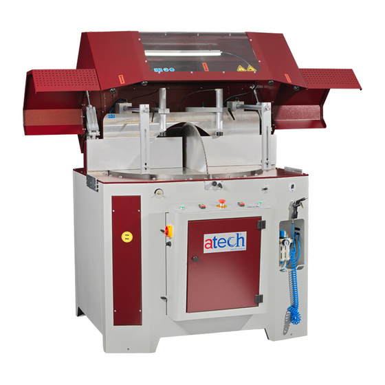
- Page 1 ATechMachinery.com CRATER – 06 A700/760 AUTOMATIC UPCUT MITER SAW USER’S MANUAL...
-
Page 2: Table Of Contents
CONTENTS 1. GENERAL INFORMATION 1. Introduction 2. Supplier Info 2. MACHINE’S DESCRIPTION AND PURPOSE OF USE 1. Machine’s Description 2. Technical Features 3. Cutting Diagram 4. Overall Dimensions 5. Electric And Pneumatic Control Board 6. Part List and Technical Drawings 7. - Page 3 Method Of Hydraucheck Air Reception Oil Completion Method 3. Spray Mist System Maintenance 4. Work Day End Care 11. TROUBLESHOOTING GUIDE 12. COMPONENTS Electric Components Hydraulic-Pneumatic Components...
-
Page 4: General Information
ATechMachinery.com info@ATechMachinery.com *In case of any technical problem please contact your nearest ATECH dealer or ATECH head office through the above mentioned phone, fax or e-mail address. *Technical labels with the model description of the machine are fixed onto the front side of each machine. -
Page 5: Technical Features
• Machine’s serial number • Voltage and frequency • Name of dealer where machine was purchased • Date of purchase • Description of the machine fault • Average daily operation period Figure 1 : Hydro-Pneumatic Cylinder Saw Blade Rising Speed Adjustment 2.2. -
Page 6: Overall Dimensions
2.4. Overall Dimensions 2.5. Electric And Pneumatic Control Board There is an electrical panel at the top, the energy must be turned off by the authorized electrician and should be checked with the diagram on the cover in case of a problem. In the lower part there is a pneumatic panel. - Page 7 Adet / Şekil / Figure Adı / Name Parça Kodu / Code Ø700 / Ø760 Saw CRA70/76-02-0001 4 kW Motor CRA70/76-04-0002 Motor Connection CRA70/76-02-0003 Block Belt Pulley CRA70/76-02-0004 Protection Part Motor Tensioner CRA70/76-02-0005 Sheet Metal Motor Tensioner Bolt CRA70/76-02-0006 Print Washer Motor Tensioner Part CRA70/76-02-0007 Belt...
- Page 8 Motor Pulley CRA70/76-02-0010 Motor Pulley Washer CRA70/76-02-0011 Coupling CRA70/76-02-0012 Washer (38-40mm) CRA70/76-02-0013 Saw Flange CRA70/76-02-0014 Saw Washer CRA70/76-02-0015 Saw Shaft Nut CRA70/76-02-0016 Saw Shaft Pipe CRA70/76-02-0017 6207 ZZ Bearing CRA70/76-02-0018 Bearing Cover CRA70/76-02-0019 Hydraucheck CRA70/76-03-0020...
- Page 9 Pneumatic Cylinder CRA70/76-03-0021 Top Cover Lifting CRA70/76-03-0022 Cylinder Saw Casing Cover CRA70/76-01-0023 Moving Front Miter CRA70/76-02-0024 Vertical Clamping CRA70/76-03-0025 Pneumatic Cylinder Horizontal Clamping CRA70/76-03-0026 Pneumatic Cylinder Standard Degree Plate Tightening CRA70/76-02-0027 Mechanism Manual Conveyor CRA70/76-01-0028 Chip Absorption CRA70/76-01-0029 Manifold...
-
Page 10: Pneumatic Circuit Scheme
2.7. Pneumatic Circuit Scheme 2.8. Electric Power Scheme 2.9. Electric Circuit Scheme... -
Page 11: Safety
3. SAFETY 3.1. Safety Information The symbols shown hereunder are necessary to be read with special attention. Not reading or observing of them may cause damage to the equipment or personal injury. The IMPORTANT symbol above is one telling to apply special care and to be careful at carrying out the specified operation. -
Page 12: General Safety Information
3.2.4.Machine should be operated only by staff members, who have read and understood the contents of this manual. 3.2.5.All directives, recommendations and general safety rules contained in this manual have to be observed fully. The machine cannot be operated in any way for purposes other than those described herein. Otherwise, the manufacturer shall not be deemed responsible for any damages or injuries. -
Page 13: Transport Of The Machine
If main connection cable is damaged during operation, do Use protective earmuffs. not touch it and disconnect the main plug from main socket. When machine is working, do Use protective gloves when not make your hand close to saw changing the saw. blade. -
Page 14: Air Pressure Setting
5.2. Instructions For Safe Connection Of The Machine To The Power Source 5.2.1. The three-phase electrical cable socket must have five inputs to the cable on the machine. 5.2.2.Use a connection cable sockets in accordance with the CE Safety Directives. 5.2.3.Check the inlet power supply before powering the machine. -
Page 15: Operation
6.6.4.Routine maintenance and scheduled maintenance should be carried out by qualified personnel after unplugging the machine and disconnecting the air supply first. 6.6.5.Ensure that the machine has been cleaned, tested and maintenance before starting to operate. 6.6.6.Check the safety devices, power cable and moving parts regularly. Don’t operate the machine before having replaced defective safety devices or faulty parts 6.6.7.Never replace the circular saw without disconnecting the air and the electrical and pneumatic power... - Page 16 CORRECT WRONG 7.1.4. Avoid touching the buttons on the clipboard at random. If you are in danger during cutting, press the emergency stop button immediately to end cutting. 7.1.5. Close the front door on the chassis and control panel and lock it with the key. (If the chassis front cover is open, the engine will not operate for safety reasons).
-
Page 17: Safe Installation Of The Saw Blade
Set the air pressure between 6-8 bars. The manometer is read as air pressure bar. If the reading on the pressure gauge is less than or equal to the desired pressure, turn the air pressure adjustment switch to the right or left to adjust the pressure to 6-8 bar. -
Page 18: Safety Installation Of The Belt
Figure 2 : Open The Control Board And The Side Figure 3 Cover Plate. Figure 4 Figure 5 Figure 6 Figure 7 9. SAFE INSTALLATION OF THE BELT Follow the instructions below to safely replace the CRATER A700/760 machine belt. 9.9.1. -
Page 19: Maintenance
9.9.4.Remove the belt cover. 9.9.5.Loosen the M10 key-head bolt with the 10 mm keys. Loosen with 10 9.9.6.Loosen the M8 screws by turning them clockwise with a 6 mm Allen key. 9.9.7.You can change the belt by loosening the motor block. 9.9.8.Once you have changed the belt, finish the process by following the procedures. -
Page 20: Oil Completion Method
7. Open the oil drain / deaeration unit plug in the shape of the photo. 8. Press gently on the top of the oil discharge unit with a flat, blunt metal (for example 3 allen). a. Foamy oil will come in the first place during the press. b. -
Page 21: Work Day End Care
3.5. Valve on the side will be turned to “ON" position when lubrication is required. Valve Closed Valve Open 3.6. Lubrication action occurs only when the saw goes up Work Day End Care Disconnect the electrical and pneumatic power connections. 4.1. -
Page 22: Components
• Check the oil level. • Observe the oil hose in the oil. • Open the valve. It may be related to the oil No lubrication. • Be sure to use the appropriate amount, oil fluidity or valve. oil. • Blow air into the end of the hose inside the drum with an blow gun.
Need help?
Do you have a question about the CRATER-06 A700 and is the answer not in the manual?
Questions and answers