Advertisement
Quick Links
IL02-SM00004EN
ORIGINAL INSTRUCTIONS
Instruction Manual
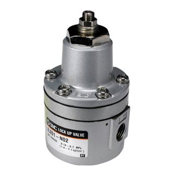
Lock-Up Valve
Series IL201/211/220
IL201
IL211
IL220
The intended use of these Lock-Up Valves is to control the air in the
secondary pressurized air system. Depending on the signal pressure the
types 201 and 211 are locking the air and the type 220 is relieving the air.
Validated according to ISO 13849.
1 Safety Instructions
These safety instructions are intended to prevent hazardous situations
and/or equipment damage. These instructions indicate the level of potential
hazard with the labels of "Caution," "Warning" or "Danger."
They are all important notes for safety and must be followed in addition to
*1)
International Standards (ISO/IEC)
, and other safety regulations.
*1)
ISO 4414: Pneumatic fluid power - - General rules relating to systems.
ISO 4413: Hydraulic fluid power - - General rules relating to systems.
IEC 60204-1: Safety of machinery - -Electrical equipment of machines.
(Part 1: General requirements)
ISO 10218-1: Manipulating industrial robots -Safety.etc.
This manual contains essential information for the protection of users and
others from possible injury and/or equipment damage.
Read this manual before using the product, to ensure correct handling,
and read the manuals of related apparatus before use.
Keep this manual in a safe place for future reference.
To ensure safety of personnel and equipment the safety instructions in
this manual must be observed, along with other relevant safety
practices.
Caution indicates a hazard with a low level of risk
Caution
which, if not avoided, could result in minor or
moderate injury.
Warning indicates a hazard with a medium level
Warning
of risk which, if not avoided, could result in death
or serious injury.
Danger indicates a hazard with a high level of risk
Danger
which, if not avoided, will result in death or serious
injury.
Warning
The compatibility of the product is the responsibility of the person
who designs the equipment or decides its specifications.
Since the product specified here is used under various operating
conditions, its compatibility with specific equipment must be decided by
the person who designs the equipment or decides its specifications
based on necessary analysis and test results. The expected
performance and safety assurance of the equipment will be
the responsibility of the person who has determined its compatibility with
the product. This person should also continuously review all
specifications of the product referring to its latest catalogue information,
1 Safety Instructions - continued
with a view to giving due consideration to any possibility of equipment
failure when configuring the equipment.
Only personnel with appropriate training should operate machinery
and equipment.
The product specified here may become unsafe if handled incorrectly.
The assembly, operation and maintenance of machines or equipment
including our products must be performed by an operator who is
appropriately trained and experienced.
Do
not
service
or
attempt
to
remove
product
machinery/equipment until safety is confirmed.
1) The inspection and maintenance of machinery/equipment should only
be performed after measures to prevent falling or runaway of the driven
objects have been confirmed.
2) When the product is to be removed, confirm that the safety measures
as mentioned above are implemented and the power from any
appropriate source is cut, and read and understand the specific product
precautions of all relevant products carefully.
3) Before machinery/equipment is restarted, take measures to prevent
unexpected operation and malfunction.
Contact SMC beforehand and take special consideration of safety
measures if the product is to be used in any of the following
conditions.
1) Conditions and environments outside of the given specifications, or
use outdoors or in a place exposed to direct sunlight.
2) Installation on equipment in conjunction with atomic energy, railways,
air navigation, space, shipping, vehicles, military, medical treatment,
combustions and recreation, or equipment in contact with food and
beverages, emergency stop circuits, clutch and brake circuits in press
applications, safety equipment or other applications unsuitable for the
standard specification described in the product catalogue.
3) An application which could have negative effects on people, property
or animals requiring special safety analysis outside the scope of ISO
13849 described in this document.
4) Use in an interlock circuit, which requires the provision of double
interlock for possible failure by using a mechanical protective function,
and periodical checks to confirm proper operation.
Always ensure compliance with relevant safety laws and standards.
All electrical work must be carried out in a safe manner by a qualified
person in compliance with applicable national regulations.
Caution
The product is provided for use in manufacturing industries.
The product herein described is basically provided for peaceful use in
manufacturing industries.
If considering using the product in other industries, consult SMC
beforehand and exchange specifications or a contract if necessary.
If anything is unclear, contact your nearest sales branch.
2 Specifications
2.1 Standard Specifications
Model
IL201
IL211
Action
Single action
Double acting
Note 1)
Signal pressure
Max.1.0 MPa
Note 1)
Set pressure range
0.14 to 0.7 MPa
Shut-off pneumatic
Max.0.7 MPa
circuit pressure
Ambient and fluid
-5 to +60 °C
temperature
Port size
Rc1/4
Note 2)
Differential
0.01 MPa
Type of fluid
Air
Fluid quality
Oil-free filtered to 5μm air
Min. operating
1 cycle / 30 days
frequency
Flow rate Cv
0.9
0.9
2 Specifications - continued
Complies with the basic and well-tried safety
Standards
principles of ISO 13849-2:2012
B
8,000 cycle
10
B
16,000 cycle
10d
Weight
0.45 kg
Table 1
Notes:
and
Note 1) Provide a differential pressure of 0.1 MPa or more between the
signal pressure and set pressure.
If the differential pressure is small, the internal part is worn out due
to the structure of this product and the bleed amount from the
exhaust port increases, which may affect the characteristics.
Note 2) Pressure difference between lock activated and lock released.
Note 3) Under SMC test conditions. The B
10
life tests. The B
figure is derived from B
10d
in EN ISO 13849-1:2008 Annex C. Contact SMC for details.
2.2 Principle of Operation
The signal air pressure enters the upper diaphragm chamber (1) to
generate a force. When this force is larger than the force generated by
compressing the adjusting spring (3), the upper diaphragm (2) is pushed
up, the exhaust port (4) is closed, and the signal air pressure enters the
lower diaphragm chamber (5) and acts the lower diaphragm (6). This
pushes down the piston (7) to open the valve. IL201 and IL211 enter the
status, in which the flow path between IN and OUT is opened. IL220 enters
the status, in which the flow path between IN1 and OUT is opened. If the
signal air pressure drops to a level below the set pressure for some reason,
the upper diaphragm (2) is pushed down, the pressure inside the lower
diaphragm (6) is exhausted from the exhaust port (4), and the valve (8) is
closed by the force of the spring (9). At this time, IN and OUT are shut
down in IL201 and IL211. In IL220, IN1 and OUT are shut down, and the
flow path between IN2 and OUT is opened. The set pressure is adjusted
with the adjusting screw (10).
Adjusting screw
Adjusting spring
Exhaust port
Upper diaphragm
Upper diaphragm chamber
Lower diaphragm chamber
Lower diaphragm
Piston
Valve
Spring
Figure 1
IL220
3 port
Adjusting screw
Adjusting spring
Exhaust port
Upper diaphragm
Upper diaphragm chamber
Lower diaphragm chamber
Lower diaphragm
Piston
Valve
Spring
1.1
Figure 2
2 Specifications - continued
Adjusting screw
Note 3)
Adjusting spring
Note 3)
Exhaust port
0.64 kg
0.7 kg
Upper diaphragm
Upper diaphragm chamber
Lower diaphragm chamber
Lower diaphragm
Piston
Valve
Spring
figure is estimated from SMC
using the assumption
10
Special products might have specifications different from those shown in
this section. Contact SMC for specific drawings. These drawings will give
the appropriate specification details and compliance with the safety
principles of ISO 13849, if applicable.
3 Installation
3.1 Installation
Do not install the product unless the safety instructions have been read
and understood.
3.2 Environment
Do not use in an environment where corrosive gases, chemicals, salt
water or steam are present.
Do not use in an explosive atmosphere.
Do not expose to direct sunlight. Use a suitable protective cover.
Do not install in a location subject to vibration or impact. Check the
product specifications.
Do not mount in a location exposed to radiant heat.
3.3 Piping
Before piping make sure to clean up chips, cutting oil, dust etc.
When installing piping or fittings, ensure sealant material does not enter
inside the port. When using seal tape, leave 1.5 to 2 threads exposed on
the end of the pipe/fitting.
Tighten fittings to the specified tightening torque.
3 Installation – continued
3.4 Lubrication
SMC products have been lubricated for life at manufacture, and do not
require lubrication in service.
If a lubricant is used in the system, use turbine oil Class 1 (no additive),
ISO VG32. Once lubricant is used in the system, lubrication must be
continued because the original lubricant applied during manufacturing
will be washed away.
4 Settings
Since connected equipment will operate when the manual override is
activated, confirm that conditions are safe prior to activation.
Figure 3
Caution
Warning
Warning
Caution
Caution
Warning
Page 1 of 3
Advertisement

Subscribe to Our Youtube Channel
Related Manuals for SMC Corporation IL211 Series


Summary of Contents for SMC Corporation IL211 Series
- Page 1 IL02-SM00004EN 1 Safety Instructions - continued 2 Specifications - continued 2 Specifications - continued with a view to giving due consideration to any possibility of equipment ORIGINAL INSTRUCTIONS failure when configuring the equipment. Complies with the basic and well-tried safety Standards ...
- Page 2 IL02-SM00004EN 5 How to Order 6 Outline Dimensions (mm) - continued 8 Limitations of Use - continued 6.3 IL220 Vacuum pads are excluded from this 1 year warranty. A vacuum pad is a consumable part, so it is warranted for a year after it is delivered.
- Page 3 Milton Keynes, Buckinghamshire MK8 0AN, United Kingdom URL : http// www.smcworld.com (Global) http// www.smceu.com (Europe) 'SMC Corporation, Akihabara UDX15F, 4-14-1, Sotokanda, Chiyoda-ku, Tokyo 101 0021 Specifications are subject to change without prior notice from the manufacturer. © 2016 SMC Corporation All Rights Reserved.
Need help?
Do you have a question about the IL211 Series and is the answer not in the manual?
Questions and answers