
Subscribe to Our Youtube Channel
Related Manuals for SMC Corporation EX260-SPN1


Summary of Contents for SMC Corporation EX260-SPN1
- Page 1 No.EX※※-OMO0030-D PRODUCT NAME SI unit for PROFINET MODEL / Series / Product Number EX260 Series...
-
Page 2: Table Of Contents
Table of Contents Safety Instructions Model Indication and How to Order Summary of Product elements Installation and Wiring Installation Wiring LED Indication and Settings Configuration Troubleshooting and Maintenance Specifications Specifications Dimensions Accessories No.EX※※-OMO0030-D... -
Page 3: Safety Instructions
Safety Instructions These safety instructions are intended to prevent hazardous situations and/or equipment damage. These instructions indicate the level of potential hazard with the labels of "Caution", "Warning" or "Danger". They are all important notes for safety and must be followed in addition to International Standards (ISO/IEC) , and other safety regulations. - Page 4 Safety Instructions Caution 1.The product is provided for use in manufacturing industries. The product herein described is basically provided for peaceful use in manufacturing industries. If considering using the product in other industries, consult SMC beforehand and exchange specifications or a contract if necessary. If anything is unclear, contact your nearest sales branch.
- Page 5 Operator This operation manual is intended for those who have knowledge of machinery using pneumatic equipment, and have sufficient knowledge of assembly, operation and maintenance of such equipment. Only those persons are allowed to perform assembly, operation and maintenance. Read and understand this operation manual carefully before assembling, operating or providing maintenance to the product.
- Page 6 Caution ■After maintenance is complete, perform appropriate functional inspections. Stop operation if the equipment does not function properly. Safety cannot be assured in the case of unexpected malfunction. ■Provide grounding to assure the noise resistance of the Serial System. Individual grounding should be provided close to the product with a short cable. ■NOTE ○Follow the instructions given below when designing, selecting and handling the product.
- Page 7 Product handling Installation •Do not drop, hit or apply excessive shock to the fieldbus system. Otherwise damage to the product can result, causing malfunction. •Tighten to the specified tightening torque. If the tightening torque is exceeded the mounting screws may be broken. IP67 protection cannot be guaranteed if the screws are not tightened to the specified torque.
- Page 8 •Mount the product in a place that is not exposed to vibration or impact. Otherwise failure or malfunction can result. •Do not use the product in an environment that is exposed to temperature cycle. Heat cycles other than ordinary changes in temperature can adversely affect the inside of the product. •Do not expose the product to direct sunlight.
-
Page 9: Model Indication And How To Order
Model Indication and How to Order EX260-SPN 1 Connector type, output specification M12 connector, 32 outputs, PNP (negative common) / source M12 connector, 32 outputs, NPN (positive common) / sink M12 connector, 16 outputs, PNP (negative common) / source M12 connector, 16 outputs, NPN (positive common) / sink Fieldbus PROFINET No.EX※※-OMO0030-D... -
Page 10: Summary Of Product Elements
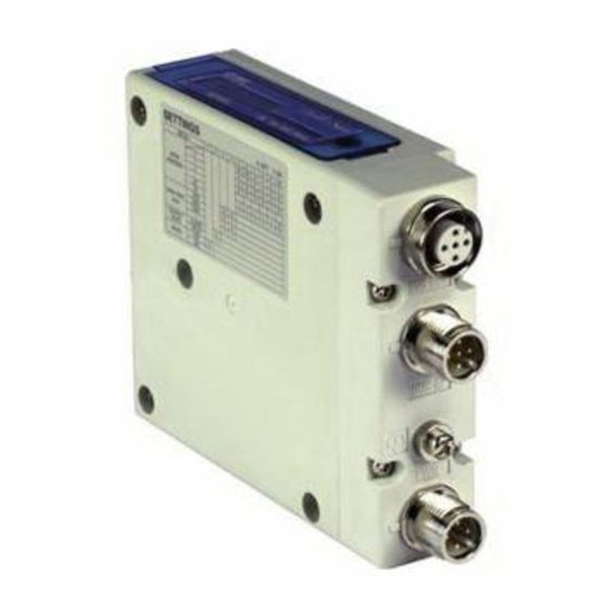
Summary of Product elements <EX260-SPN1/-SPN2/-SPN3/-SPN4> Element Description 1 Fieldbus interface connector PROFINET connection PORT 2. (BUS OUT/Port2) (M12 4-pin socket, D-coded) 1 Fieldbus interface connector PROFINET connection PORT 1. (BUS IN/Port1) (M12 4-pin socket, D-coded) 1 Power supply with load voltage for valves and operating voltage for SI unit. -
Page 11: Installation And Wiring
Installation and Wiring ■Installation Connect valve manifold to the SI unit. •Dimensions for installation n: number of valve stations 120.7 136.7 152.7 168.7 184.7 200.7 216.7 232.7 248.7 264.7 280.7 296.7 312.7 328.7 344.7 (mm) The above table shows dimensions as an example for the SY5000 series valve manifold. Connectable valve manifolds are the same as for EX250 series SI unit. -
Page 12: Wiring
■Wiring Select the appropriate cables to mate with the connectors mounted on the SI unit. Refer to Accessories (page 34). ○Fieldbus interface connector layout BUS OUT/Port2: M12 4-pin socket, D-coded (SPEEDCON) Designation Description Transmit Data + Receive Data + Transmit Data - Receive Data - BUS IN/Port1: M12 4-pin socket, D-coded (SPEEDCON) Designation... - Page 13 ○Power supply connector layout PWR: M12 5-pin plug, A-coded (SPEEDCON) Designation Description SV24 V +24 V for solenoid valve SV0 V 0 V for solenoid valve SI24 V +24 V for SI unit operation SI0 V 0 V for SI unit operation Unused The M12 connector cable has two types, SPEEDCON compatible and non-compatible.
- Page 14 Power-supply line for solenoid valve and power-supply line for SI unit operation are isolated. Be sure to supply power, respectively. Either single-source power or two different power supplies can be used. : Pay attention not to exceed the tolerance range of power supply voltage. -13- No.EX※※-OMO0030-D...
- Page 15 ○Ground terminal Connect the ground terminal to ground. Resistance to ground should be 100 ohms or less. -14- No.EX※※-OMO0030-D...
-
Page 16: Led Indication And Settings
LED Indication and Settings ○LED indication LED Status Description Operating normally •SI unit-related diagnostic error is detected (load power for the valve is not supplied or outside tolerance range) Red ON •The configuration information registered in the master and the number of output points does not match (BF flashing). -
Page 17: Configuration
An applicable GSD file is required to configure the SI unit in the PROFINET network. Please download the latest GSD file from the SMC website (URL http://www.smcworld.com). GSD file Model No. GSD file EX260-SPN1/-SPN2 GSDML-V2.3-SMC-EX260-.xml EX260-SPN3/-SPN4 The network configuration procedure using the SIEMENS STEP7 version V5.5 master software is described below. - Page 18 Browse and select the GSD file stored on the PC. ○Device name assignment Connect the SI unit and execute "PLC" – "Edit Ethernet Node" from the HW Configuration window. -17- No.EX※※-OMO0030-D...
- Page 19 Enter the MAC address if it is known, or execute "Browse" and select the MAC address of the connected SI unit. After entering the MAC address, assign the Device name. -18- No.EX※※-OMO0030-D...
- Page 20 ○Remote I/O configuration Drag and drop the folder for the "EX260-SPN1/2" or "EX260-SPN3/4" from the HW catalogue, and place it on the PROFINET line on the PN master. •EX260-SPN1/2: SI unit with 32 outputs, EX260-SPN1 or EX260-SPN2 1 This SI unit can be used with both firmware version 1.0.0 and 2.1.1 , but the MRP function is not available.
- Page 21 "EX260-SPN (EX260-SPN-1, EX260-SPN-2, and so on)" should be entered in the Device name box for each EX260-SPN1/2 or EX260-SPN3/4 set with the hardware configuration. The same name must be used for the connected SI unit device name (page 18) and the device name set in the hardware configuration.
- Page 22 ○Diagnostic parameters The diagnostic parameters of the EX260-SPN1/2 (32 outputs) are as follows: Name Range of values Default Description If the solenoid valve supply voltage is 19 V Enable Valve Power Disable or less, it is possible to send an error state Disable to the master.
- Page 23 ○Setting of diagnostic parameters Select the EX260-SPN icon from the dialogue of the HW configuration window. Double click the slot 0 and set the diagnostic parameters in the "Properties" window. -22- No.EX※※-OMO0030-D...
- Page 24 ○FSU (Fast Start Up) function The EX260-SPN supports the FSU function. The connected master controller must also support the FSU function in order to enable the EX260-SPN FSU function. •Configuration of the controller to enable the FSU function Double click the PROFINET port of the controller which is connected to the EX260-SPN to enable the FSU function.
- Page 25 •Configuration of the EX260-SPN to enable the FSU function Select the EX260-SPN icon from the dialogue of the HW configuration window. Double click the Slot X1 Interface and in the "General" window check "Prioritized startup". Double click the port (P1 (BUS IN) or P2 (BUS OUT)) which enables the EX260-SPN FSU function. Select "Options"...
- Page 26 ○Output number assignment Output data : The output numbering refers to the solenoid position on the manifold and starts at zero. : Standard wiring of the manifold is for double-solenoid valves and the output number starts at the A side and then B side in that order as shown in the figure a.
-
Page 27: Troubleshooting And Maintenance
Troubleshooting and Maintenance ○Troubleshooting chart When any malfunction is observed, it is recommended to perform the following troubleshooting. SI unit SI unit Refer to fault malfunction PWR LED is OFF No.1 SI unit Refer to fault PWR (V) LED is OFF No.2 SI unit Refer to fault... - Page 28 Troubleshooting table Fault No.1 Fault Probable cause Recommended error handling Recommended action Re-tighten the power cable. Defective power (Replace the cable if it is broken) Check the condition of the power cable cable wiring for SI wiring to the SI unit. Correct the power cable wiring SI unit unit operation...
- Page 29 Fault No.5 Fault Probable cause Recommended error handling Recommended action Tighten the communication Check the communication cable cable connection. connections and check for broken wires. (Replace the cable if it is broken) Check that the configuration information Configure the SI unit in the PN PROFINET registered in the PN master matches the SI unit BF...
- Page 30 Fault No.8 Fault Probable cause Recommended error handling Recommended action Tighten the screws with the Poor connection Check if there are any loose screws making specified tightening torque between SI unit and the connection between the SI unit and the (i.e.
- Page 31 ○Maintenance Replacement of the SI unit •Remove the M3 hexagon screws from the SI unit and release the SI unit from the valve manifold. •Replace the SI unit. •Tighten the screws with the specified tightening torque. (0.6 Nm) Precautions for maintenance (1) Be sure to switch off the power.
-
Page 32: Specifications
22.8 to 26.4 VDC power supply Solenoid valve power supply 2.0 A or less, according to the solenoid valve station voltage range specification EX260-SPN1/-SPN3 PNP (negative common) / source Output type EX260-SPN2/-SPN4 NPN (positive common) / sink Solenoid valve Solenoid valve with surge voltage suppressor of... - Page 33 Connectable valve series Valve Series SY series SY3000, SY5000 VQC series VQC1000, VQC2000, VQC4000 SV series SV1000, SV2000, SV3000 (10 type tie-rod base) S0700 series S0700 The valve manifolds that can be connected are the same as those connectable to EX250 series. -32- No.EX※※-OMO0030-D...
-
Page 34: Dimensions
■Dimensions •If a fieldwireable connector is used for the power supply connection, and the SI unit is installed directly to a valve manifold, the cable connector’s outer diameter should be 16 mm or less. If it is a larger diameter, the connector will interfere with the mounting surface. Recommended cables are specified in the accessories section, on page 34. -
Page 35: Accessories
Accessories ○Fieldbus interface connector (1) Cable with communication connector (SPEEDCON) Part number: PCA-1446566 Item Specifications Pin No. Cable colour: Signal Yellow : TD+ M12 Straight Connector (SPEEDCON) White : RD+ Cable length 5000 mm Orange: TD- 6.5 mm Cable O.D. Blue : RD- Nominal cross section... - Page 36 (3) Cable with communication connector Part number: EX9-AC 01 0EN-PSRJ Cable length (L) 1000 [mm] 2000 [mm] 3000 [mm] 5000 [mm] 10000 [mm] Item Specifications M12 Straight Connector RJ45 6.4 mm Cable O.D. Nominal cross section AWG26 Min. bending radius (Fixed) 26 mm (4) Seal cap Part number: EX9-AWTS...
- Page 37 ○Power supply connector (1) Cable with power supply connector Part number: EX500-AP0 1 0- S Connector specifications Straight Angle Cable length (L) 1000 [mm] 5000 [mm] EX500-AP0#0-S EX500-AP0#0-A Item Specifications Pin No. Cable colour: Signal 6 mm Cable O.D. Brown: 24 VDC (For solenoid valve) Nominal cross section AWG22 White : 0 V (For solenoid valve)
- Page 38 (2) Cable with power supply connector (SPEEDCON) Part number: PCA-140180 4 Cable length (L) 1500 [mm] 3000 [mm] 5000 [mm] Item Specifications Pin No. Cable colour: Signal Brown: 24 VDC (For solenoid valve) M12 Straight Connector (SPEEDCON) White : 0 V (For solenoid valve) 5 mm Cable O.D.
- Page 39 4-14-1, Sotokanda, Chiyoda-ku, Tokyo 101-0021 JAPAN Tel: + 81 3 5207 8249 Fax: +81 3 5298 5362 http://www.smcworld.com Note: Specifications are subject to change without prior notice and any obligation on the part of the manufacturer. © 2011-2017 SMC Corporation All Rights Reserved No.EX※※-OMO0030-D...
Need help?
Do you have a question about the EX260-SPN1 and is the answer not in the manual?
Questions and answers