Table of Contents
Advertisement
Quick Links
Advertisement
Table of Contents

Related Manuals for ATEN RCM101A


Summary of Contents for ATEN RCM101A
- Page 1 Single Port KVM over IP RCM101A User Manual www.aten.com...
- Page 2 RCM101A User Manual EMC Information FEDERAL COMMUNICATIONS COMMISSION INTERFERENCE STATEMENT: This equipment has been tested and found to comply with the limits for a Class A digital device, pursuant to Part 15 of the FCC Rules. These limits are designed to provide reasonable protection against harmful interference when the equipment is operated in a commercial environment.
-
Page 3: Rohs
RCM101A User Manual KCC Statement: RoHS This product is RoHS compliant. -
Page 4: User Information
RCM101A User Manual User Information Online Registration Be sure to register your product at our online support center: International http://eservice.aten.com Telephone Support For telephone support, call this number: International 886-2-8692-6959 China 86-400-810-0-810 Japan 81-3-5615-5811 Korea 82-2-467-6789 North America 1-888-999-ATEN ext 4988... -
Page 5: Package Contents
© Copyright 2020 ATEN® International Co., Ltd. Manual Date: 2020-09-09 ATEN and the ATEN logo are registered trademarks of ATEN International Co., Ltd. All rights reserved. All other brand names and trademarks are the registered property of their respective owners. -
Page 6: Table Of Contents
RCM101A User Manual Contents EMC Information..........ii RoHS . - Page 7 RCM101A User Manual Chapter 3. Local Console and OSD Operation Local Console ..........19 Laptop USB Console.
- Page 8 RCM101A User Manual SNMP Server ........46 Syslog Server .
- Page 9 RCM101A User Manual The Message Board ........88 Buttons on the Top .
- Page 10 RCM101A User Manual OpenLDAP ..........119 OpenLDAP Server Installation .
- Page 11 RCM101A User Manual General Operation........151 Windows .
-
Page 12: About This Manual
RCM101A User Manual About this Manual This User Manual is provided to help you get the most from your RCM101A. It covers all aspects of installation, configuration and operation. An overview of the information found in the manual is provided below. -
Page 13: Conventions
RCM101A User Manual Conventions This manual uses the following conventions: Monospaced Indicates text that you should key in. Indicates keys you should press. For example, [Enter] means to press the Enter key. If keys need to be chorded, they appear together in the same bracket with a plus sign between them: [Ctrl+Alt]. -
Page 14: Terminology
Terminology Throughout the manual we make reference to the terms Local and Remote in regard to the operators and equipment deployed in a RCM101A installation. Depending on the point of view, users and servers can be considered Local under some circumstances, and Remote under others: ... -
Page 15: Product Information
For information about all ATEN products and how they can help you connect without limits, visit ATEN on the Web or contact an ATEN Authorized Reseller. Visit ATEN on the Web for a list of locations and telephone numbers: International... - Page 16 RCM101A User Manual This Page Intentionally Left Blank...
-
Page 17: Chapter 1 Introduction
Internet browser or Windows and Java based application programs. The RCM101A connects to the local area network using standard Cat 5e cable, then uses a custom KVM cable to connect to a local KVM switch or server. - Page 18 RCM101A (KVM OSD display or server's desktop) and he can control it from his console just as if he were there.
-
Page 19: Features And Benefits
* Cascade-compatible KVM Switches include the following: CS1308, CS1316, CS1754*, CS1758*, CS1708A, CS1716A • Some of the RCM101A’s features may not be supported, depending on the functionality of the cascaded KVM switch. (For example, some switches do not support virtual media.) •... -
Page 20: Management
RCM101A User Manual Management Laptop USB Console (LUC) – a dedicated USB port directly connects to laptop for easy console operation Easy configuration through local console OSD Up to 64 user accounts – up to 32 users can simultaneously share control ... -
Page 21: Virtual Media
1. Introduction Flexible encryption design allows users to choose any combination of 56- bit DES, 168-bit 3DES, 256-bit AES, 256-bit RC4 or Random for independent keyboard/mouse, video, and virtual media data encryption Supports IP/MAC Filter Supports password protection ... -
Page 22: System Requirements
For PS/2 KVM Cable Connections: 6-pin Mini-DIN keyboard and mouse ports Cables A custom KVM cable set (USB; PS/2) to link the RCM101A to a server or KVM switch are provided with this package. Custom KVM cable sets are available in various lengths, as shown in the... -
Page 23: Video
RCM101A include Windows XP or later, and other systems capable of running Sun's Java Runtime Environment (JRE) 6, Update 3, or higher (Linux, Mac, Sun, etc.). Supported operating systems for servers that connect to the RCM101A are shown in the table, below: Version... -
Page 24: Browsers
6.5 or later OS X 10.7 or later 6.2 or later Browsers The browsers and the versions shown in the table below have been tested to support RCM101A login for the users: Browser Version 8, 10, 11 Firefox 33, 45.2.0, 47.0 Safari* 9.1.3... -
Page 25: Components
3 4 5 6 Component Description LAN Port The Cat 5e/6 cable that connects the RCM101A to the LAN plugs in here. Laptop USB Use the USB cable provide with this package to connect a laptop to this port for console access. -
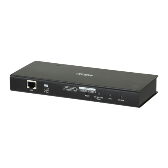
Page 26: Rear View
The KVM cable (supplied with this package) that links the RCM101A to your server or KVM switch plugs in here. PS/2 - USB The RCM101A can be accessed via a local console as well Console Port as over the Net. The cable for the local console (keyboard, monitor, mouse) plugs in here. -
Page 27: Custom Console Cable
1. Introduction Custom Console Cable USB Keyboard USB Mouse Video PS/2 Keyboard PS/2 Mouse Note: You can use any combination of keyboard and mouse connections. For example, you can use a PS/2 keyboard with a USB mouse. - Page 28 RCM101A User Manual This Page Intentionally Left Blank...
-
Page 29: Mounting
Mounting Rack Mounting For convenience and flexibility, the RCM101A can be mounted on a system rack. To rack mount the unit do the following: 1. Remove the two original screws from the bottom of the unit (near the rear of the unit). -
Page 30: Din Rail Mounting
DIN Rail Mounting To mount the RCM101A on a DIN rail: 1. Screw the mounting bracket to the back of the RCM101A as described in steps 1 and 2 of the wall mounting procedure. 2. Use the larger screws supplied with the Rack Mount Kit to screw the DIN rail brackets to the mounting bracket –... -
Page 31: Installation
2. Hardware Setup Installation To install the RCM101A, refer to the installation diagrams on the next two pages (the numbers correspond to the numbers of the steps), and do the following: 1. Use the Custom Console Cable provided with this package to connect the RCM101A’s PS/2-USB Console Port, to the local console keyboard,... - Page 32 AC power source. This completes the hardware installation, and you are ready to start up. Note: When starting up, be sure to first power on the RCM101A, then power on the server or KVM switch.
- Page 33 2. Hardware Setup CL5708-CL5716 CS1708A-CL1716A RCM101A...
- Page 34 RCM101A User Manual This Page Intentionally Left Blank...
-
Page 35: Local Console And Osd Operation
RCM101A’s basic settings when accessed via local console. Local Console Use the keyboard, mouse and monitor to directly access and operate the local console port. The RCM101A is able to split the signal to both the local and remote consoles. Laptop USB Console To use the mini USB port for Laptop USB Console (LUC) operations, simply connect the USB 2.0 cable between the RCM101A and your laptop as detailed... - Page 36 RCM101A User Manual 3. Select the “USB Mass Storage Device” and click Connect. 4. Enter the Username/Password (administrator/password) and click OK. 5. If the login was successful, the Remote View button becomes active. 6. Click Remote View to bring up the Laptop Console Main Page.
- Page 37 Chapter 3. Local Console and OSD Opera- An example of the Laptop Console main page is shown. The Laptop Console Main Page is similar to the Web Configuration. See Web Configuration, page 31, for further details.
-
Page 38: Osd Overview
OSD Overview The On Screen Display (OSD) is a menu driven method to view and configure the RCM101A’s basic settings. To display the Main Screen, tap the OSD hotkey twice. The default hotkey is [Scroll Lock]. You can change the hotkey to the Ctrl key or the Alt key if you like (see User Preferences, page 64). -
Page 39: Osd Navigation
Chapter 3. Local Console and OSD Opera- When you log in to the OSD, the RCM101A’s main menu appears: OSD Navigation The OSD uses a menu that is navigated using they keyboard or mouse. To Logout of the OSD menu, click the X at the upper right corner of the OSD Window or press Esc. -
Page 40: Device Information
Firmware Version Indicates the RCM101A's current firmware version level. New versions of the RCM101A's firmware can be downloaded from our website as they become available (see Upgrade Main Firmware, page 35). You can reference this number to see if there are newer versions available on the website. -
Page 41: Set Ip Address
Chapter 3. Local Console and OSD Opera- Set IP Address The Set IP Address screen is used to specify the RCM101A's network environment. The RCM101A can have its IPv4 address assigned dynamically (DHCP), or it can be given a fixed IP address. -
Page 42: Disable Dev Authentication
IP address (192.168.0.60). 2. If the RCM101A is on a network that uses DHCP to assign network addresses, and you need to ascertain its IP address, see IP Address Determination, page 137, for information. -
Page 43: Chapter 4. Browser Login
Logging In To operate the RCM101A from an Internet browser, begin by logging in: 1. Open your browser and specify the IP address of the RCM101A you want to access in the browser's URL location bar. Note: 1. For security purposes, a login string may have been set by the administrator. - Page 44 RCM101A User Manual The RCM101A login page appears: 3. Provide a valid Username and Password (set by the RCM101A administrator), and click Login to continue. Note: 1. If you are the administrator, and are logging in for the first time, use the default Username: administrator;...
-
Page 45: Main Webpage Elements
The screen to the right of the sidebar is your main work area. The screens that appear reflect your sidebar menu choices, and allow you to make changes to the RCM101A. Note: If a user doesn’t have permission to perform a particular activity, the menu for that activity doesn’t appear. -
Page 46: Sidebar Submenu
Windows Client from your ATEN provider. For more details, refer to The Windows Client Viewer on page 69. Click this icon to log out and end your RCM101A session. For security reasons, it is important to log out when your session ends. -
Page 47: Chapter 5. Web Configuration
Chapter 5 Web Configuration Introduction Web configuration of the RCM101A using a web browser is divided into 3 sections: Basic Settings, Advanced Settings, and Preferences. Each section is listed on the sidebar with sub-menus that are used to configure the RCM101A’s operating environment. -
Page 48: Basic Settings
RCM101A User Manual Basic Settings This section provides 3 sub-menus: User Management, Sessions, and Maintenance, used to manage user accounts and perform system maintenance on the RCM101A. User Management The User Management page is used to create and manage user profiles. Up to 64 user profiles can be established. - Page 49 View Only: Checking View Only allows a user to view the video of the display of the computers attached to the ports of the KVM switch connected to the RCM101A, but they are not allowed to perform any operations on the computers.
-
Page 50: Sessions
IP refers to the IP address that the user has logged in from. Login Time refers to the date and time that the account logged in. Client refers to the means the user employed to connect to the RCM101A (Browser, WinClient AP, JavaClient AP, etc.). -
Page 51: Maintenance
To upgrade the firmware, do the following: 1. Download the new firmware file to your computer. 2. Open your browser; log in to the RCM101A; and click the Maintenance link to bring up the Firmware File dialog box: 3. Click Browse and navigate to the directory that the new firmware file is in and select the file. -
Page 52: Backup
3. When the browser asks what you want to do with the file, select Save; then save it in a convenient location. Note: The RCM101A saves all its backup files as Sysconfig.cfg. If you want to save more than one backup file, simply rename the file to... -
Page 53: Restore
Backed up User Account and Configuration information can be restored in the Restore section of the page. Information currently configured on the RCM101A will be replaced with the information that you choose to restore. To restore a previous backup, do the following: 1. -
Page 54: Ping Host
RCM101A User Manual Ping Host The Ping Host page allows you to ping the IP address of a device to see if it’s responding on the network. To ping a device, enter the IP address and click Ping. -
Page 55: Advanced Settings
Device Name To make it easier to manage installations that have more than one RCM101A, each one can be given a name. To assign a name for the RCM101A, key in one of your choosing here (50 characters max.), then click Save. -
Page 56: Network
IP Installer utility. See page 137 for IP Installer details. Note: 1. If you select View Only, you will be able to see the RCM101A in the IP Installer’s Device List, but you will not be able to change the IP address. -
Page 57: Service Ports
IP address when they login from a WinClient or Java Client AP program. If not, an invalid port number (or no port number) is specified, the RCM101A will not be found. An explanation of the fields is given in the table below:... -
Page 58: Ipv4 Settings
IP address (192.168.0.60.) 2. If the RCM101A is on a network that uses DHCP to assign network addresses, and you need to ascertain its IP address, see IP Address Determination, page 137, for information. -
Page 59: Ipv6 Settings
IP], radio button and fill in the IPv6 Address, Subnet Prefix Length and Default Gateway. Note: If the RCM101A is on a network that uses DHCP to assign network addresses, and you need to ascertain its IP address, see IP Address Determination, page 137, for information. -
Page 60: Ddns
4. Key in the Username and Password that authenticates you with your DDNS service. 5. In the DDNS Retry Time field, key in how many hours (between 1–128) the RCM101A waits before it tries to reconnect to the DDNS server, when the RCM101A fails to connect. Network Transfer Rate... -
Page 61: Anms - Event Destination
It is divided into several sections, described in the sections that follow. SMTP Settings To have the RCM101A email reports from the SMTP server to you, do the following: 1. Enable the Enable report from the following SMTP Server, and key in the SMTP Server IP address and Service Port. -
Page 62: Log Server
Address, Report system reboot, Report user login and Report user logout. Log Server Important transactions that occur on the RCM101A, such as logins and internal status messages, are kept in an automatically generated log file. See Chapter 7, The Log Server, for details on setting up the log server. -
Page 63: Syslog Server
Note: The following SNMP trap events are sent: System Power On, Login Failure, and System Reset. Syslog Server To record all the events that take place on the RCM101A and write them to a Syslog server, do the following: 1. Check Enable. -
Page 64: Anms - Authentication
2. Fill in the IP addresses and port numbers for the Preferred and Alternate RADIUS servers. 3. In the Timeout field, set the time in seconds that the RCM101A waits for a RADIUS server reply before it times out. 4. In the Retries field, set the number of allowed RADIUS retries. -
Page 65: Ad/Ldap Settings
For LDAP, the default port number is 389; for LDAPS, the default port number is 636. Timeout Set the time in seconds that the RCM101A waits for an LDAP or LDAPS server reply before it times out. Admin DN / Name Consult the LDAP / LDAPS administrator to ascertain the appropriate entry for this field. -
Page 66: Security
RCM101A User Manual Security The Security page controls access to the RCM101A. Login Failures For increased security, the Login Failures section allows administrators to set policies governing what happens when a user fails to log in successfully. To set the Login Failures policies, check the Enable checkbox (the default is for Login Failures to be enabled). -
Page 67: Filter
If any filters have been configured, they appear in the IP Filter and/or MAC Filter list boxes. IP and MAC Filters control access to the RCM101A based on the IP and/or MAC addresses of the computers attempting to connect. A maximum of 100 IP filters and 100 MAC filters are allowed. -
Page 68: Adding Filters
RCM101A User Manual Adding Filters To add an IP filter, do the following: 1. Click Add. A dialog box similar to the one below appears: 2. Key the address you want to filter in the From: field. To filter a single IP address, key the same address in the To: field. - Page 69 Delete. Login String The Login String lets the Administrator specify a login string that users must include (in addition to the IP address) when they access the RCM101A with a browser. For example: 192.168.0.126/RCM101A The following characters are allowed: 0–9 a–z A–Z ~ ! @ $ ^ &...
-
Page 70: Account Policy
RCM101A User Manual Account Policy In the Account Policy section, system administrators can set policies governing usernames and passwords. The meanings of the Account Policy entries are explained in the table below: Entry Explanation Minimum Username Length Sets the minimum number of characters required for a username. -
Page 71: Encryption
5. Web Configuration Encryption These flexible encryption alternatives for keyboard/mouse, video, and virtual media data let you choose any combination of DES; 3DES; AES; RC4; or a Random cycle of any or all of them. Enabling encryption will affect system performance – no encryption offers the best performance;... -
Page 72: Working Mode
Working Mode Use this section to set the working mode parameters. Enable ICMP so that the RCM101A can be pinged. If it is not enabled, the device cannot be pinged. The default is Enabled. Enable Multiuser Operation to permit more than one user to log into the RCM101A at the same time. -
Page 73: Private Certificate
For enhanced security, the Private Certificate section allows you to use your own private encryption key and signed certificate, rather than the default ATEN certificate. There are two methods for establishing your private certificate: generating a self-signed certificate;... -
Page 74: Certificate Signing Request
RCM101A User Manual Certificate Signing Request The Certificate Signing Request (CSR) section provides an automated way of obtaining and installing a CA signed SSL server certificate. To perform this operation, do the following: 1. Click Create CSR. The following dialog box appears: 2. - Page 75 Click Browse to locate the file; then click Upload to store it on the RCM101A. Note: When you upload the file, the RCM101A checks the file to make sure the specified information still matches. If it does, the file is accepted;...
-
Page 76: Date/Time
Set the parameters according to the information below. Time Zone To establish the time zone that the RCM101A is located in, drop down the Time Zone list and choose the city that most closely corresponds to where it is at. -
Page 77: Date
5. Web Configuration Date Select the month from the drop-down list box. Click < or > to move backward or forward by one year increments. In the calendar, click on the day. Time To set the time, key in the numbers using the 24 hour HH:MM:SS format. ... -
Page 78: Customization
Use this section to edit the device settings. If Force All to Grayscale is enabled, the remote displays of all devices connected to the RCM101A are changed to grayscale. This can speed up I/ O transfer in low bandwidth situations. - Page 79 Reset: After making any network changes, be sure Reset on exit has been enabled (there is a check in the checkbox), before logging out. This allows network changes to take effect without having to power the switch off and Click Reset Default Values to use the default factory settings of the RCM101A.
-
Page 80: Preferences
Selecting Auto causes the RCM101A to display the pages in the same language to which the browser is set. If your browser is set to a non-supported language, the RCM101A looks to what your server’s operating system is set to. If the operating system is set to a supported language it will use that language to display its pages. -
Page 81: Password
Click Change Password to apply your settings. The RCM101A logs all the events that take place on it. Following a reset, it writes them to a log file, which can be used as a searchable database with a log server. -
Page 82: Remote Console
RCM101A User Manual Remote Console This section provides a preview screen that shows a snapshot of the server’s display, as follows: Clicking Refresh updates the snapshot of the remote display. Exit Macro The Exit Macro panel contains a drop-down list box of user created System macros: Select the Exit Macro you would like to use and click Save. - Page 83 5. Web Configuration 1. Click the button of the AP you want to download. 2. Follow the on-screen instructions to complete the installation and have the program icon placed on your desktop. For more information on the Windows Client AP and Java Client AP, refer to Chapter 6 on page 91.
-
Page 84: About
RCM101A User Manual About Click About to view the RCM101A’s firmware version. Logout Click the Logout icon when you are done configuring the RCM101A’s operating environment. This logs you out of the RCM101A GUI. -
Page 85: The Windows Client Viewer
Chapter 6 The Windows Client Viewer Starting Up The RCM101A has a standalone windows application that opens a window on the user’s desktop containing the remote server’s (RCM unit) display. Follow the steps below to reach the remote server’s display. - Page 86 RCM101A User Manual Server Use this section if you wish to connect to a RCM101A at a remote location. Enter the IP address and the port of the unit and click Connect. If you don't know the Port number, contact the Administrator.
-
Page 87: Navigation
6. The Windows Client Viewer Navigation You can work on the remote computer via the screen display, just as if it were your local system. You can maximize the window, drag the borders to resize the window; or use the scrollbars to move around the screen. ... -
Page 88: The Winclient Control Panel
RCM101A User Manual The WinClient Control Panel The WinClient control panel is hidden at the upper center of the screen. It becomes visible when you move the mouse pointer over it: Note: 1. The above image shows the complete Control Panel. The icons that appear can be customized. -
Page 89: Control Panel Functions
6. The Windows Client Viewer Control Panel Functions The Control Panel functions are described in the table below. Icon Function This is a toggle. Click to make the Control Panel persistent – i.e., it always displays on top of other screen elements. Click again to have it display normally. - Page 90 RCM101A User Manual Icon Function Click to bring up the on-screen keyboard (see The On-Screen Keyboard, page 95, for details). Click to select the mouse pointer type. Note: This icon changes depending on which mouse pointer type is selected (see Mouse Pointer Type, page 97, for details).
-
Page 91: Macros
6. The Windows Client Viewer Macros The Macros icon provides access to three functions found in the Macros dialog box: Hotkeys, User Macros, and System Macros. Each of these functions is described in the following sections. Hotkeys Various actions, corresponding to clicking the Control Panel icons, can be accomplished directly from the keyboard with hotkeys. - Page 92 RCM101A User Manual An explanation of the Hotkey actions is given in the table below: Action Explanation Exit remote location Exits the remote view and goes back to the web browser Main Page. This is equivalent to clicking the Exit icon on the Control Panel.
-
Page 93: User Macros
6. The Windows Client Viewer User Macros User Macros are used to perform specific actions on the remote server. To create the macro, do the following: 1. Select the User Macros radio button, then click Add. 2. In the dialog box that comes up, replace “NewMacro” with a name of your choice for the macro:... - Page 94 RCM101A User Manual 3. Click Record. The dialog box disappears, and a small panel appears at the top left of the screen: 4. Press the keys for the macro. To pause macro recording, click Pause. To resume, click Record again.
-
Page 95: Running Macros
6. The Windows Client Viewer 5. If you haven’t brought up the Show dialog, click Done when you have finished recording your macro. You return to the Macros dialog box with the macro keys that you pressed displayed in the Macro column: 6. - Page 96 RCM101A User Manual If you choose Play With Time Control, the macro waits for the amount of time between key presses that you took when you created it. Click on the arrow next to Play to make your choice.
-
Page 97: Search
6. The Windows Client Viewer Search Search, at the bottom of the dialog box, lets you filter the list of macros that appear in the large upper panel for you to play or edit. Click a radio button to choose whether you want to search by name or by key; key in a string for the search;... - Page 98 RCM101A User Manual 3. Click Record. The dialog box disappears, and a small panel appears at the top left of the screen: 4. Press the keys for the macro. To pause macro recording, click Pause. To resume, click Record again.
- Page 99 Once the system macros have been created, you can choose to run any one of them upon logging out of the RCM101A. System macros will only execute when the last user has logged out of the viewer (see Exit Macro, page 66, for details).
-
Page 100: Video Settings
RCM101A User Manual Video Settings The Video Settings dialog box allows you to adjust the placement and picture quality of the remote screen display on your monitor. The meanings of the adjustment options are given in the table below: Option... - Page 101 Depending on the network bandwidth, a high value may adversely effect response time. Enable Refresh The RCM101A can redraw the screen every 1 to 99 seconds, eliminating unwanted artifacts from the screen. Select Enable Refresh and enter a number from 1 through 99. The RCM101A will redraw the screen at the interval you specify.
-
Page 102: Gamma Adjustment
RCM101A User Manual Option Usage Detect Tolerance This setting also relates to video quality. It governs detecting or ignoring pixel changes. A high setting can result in a lower quality display due to less data transfer. A lower setting will result in... - Page 103 6. The Windows Client Viewer This section allows you to adjust the video display's gamma level. Click and drag the diagonal line at as many points as you wish to achieve the display output you desire. If a gamma level is desirable, click Save As to save the current configuration as one of the four user-defined configurations.
-
Page 104: The Message Board
RCM101A User Manual The Message Board To alleviate the possibility of access conflicts resulting from multiple user logins, the RCM101A provides a message board that allows users to communicate with each other: Buttons on the Top The buttons on the top are toggles. Their actions are described in the table... -
Page 105: Message Display Panel
6. The Windows Client Viewer Message Display Panel Messages that users post to the board - as well as system messages - display in this panel. If you disable Chat, however, messages that get posted to the board won't appear. Compose Panel Key in the messages that you want to post to the board in this panel. -
Page 106: Virtual Media
RCM101A User Manual Virtual Media The Virtual Media feature allows a drive, folder, image file, or removable disk on a local client computer to appear and act as if it were installed on the remote server. Virtual Media also supports a smart card reader function that allows a reader plugged into a local client computer to appear as if it were plugged into the remote server. - Page 107 6. The Windows Client Viewer Depending on your selection, additional dialog boxes appear enabling you to select the drive, file, folder, or removable disk you desire. See Virtual Media Support, page 158 for details about mounting these media types. 3. If your device only supports full speed USB, check the Disable High Speed USB Operation Mode checkbox.
- Page 108 RCM101A User Manual 2. See Virtual Media Support, page 158, for a list of supported virtual media types. 3. To remove an entry from the list, select it and click Remove. 4. After you have made your media source selections, click Mount. The dialog box closes.
-
Page 109: Smart Card Reader
6. The Windows Client Viewer Smart Card Reader The smart card reader function allows a reader plugged into a local client computer’s USB port to be redirected, and appear as if it were plugged into the remote server. One purpose of smart cards (Common Access Cards, for example), is to allow authentication to the remote server from the local client. -
Page 110: Zoom
RCM101A User Manual Zoom The Zoom icon controls the zoom factor for the remote view window. Settings are as follows: Setting Description 100% Sizes and displays the remote view window at 100%. Sizes and displays the remote view window at 75%. -
Page 111: The On-Screen Keyboard
6. The Windows Client Viewer The On-Screen Keyboard The RCM101A supports an on-screen keyboard, available with a PC or Sun layout and in multiple languages, with all the standard keys for each supported language. Click this icon to pop up the on-screen keyboard: One of the major advantages of the on-screen keyboard is that if the keyboard languages of the remote and local systems aren’t the same, you don’t have to... - Page 112 RCM101A User Manual To display/hide the expanded keyboard keys, click the arrow to the right of the language list arrow.
-
Page 113: Mouse Pointer Type
6. The Windows Client Viewer Mouse Pointer Type The RCM101A offers a number of mouse pointer options when working in the remote display. Click this icon to select the type that you would like to work with: Note: The icon on the Control Panel changes to match your choice. -
Page 114: Mac Considerations
RCM101A User Manual Mac Considerations For Mac systems, there is a second DynaSync setting to choose from. If the default synchronization result is not satisfactory, you can try the Automatic For Mac 2 setting. To select Mac 2, right click in the text area ... -
Page 115: Customize Control Panel
6. The Windows Client Viewer Customize Control Panel Clicking the Customize Control Panel icon brings up a dialog box that allows you to configure the items that appear on the Control Panel, as well as its graphical settings: The dialog box is organized into six main sections as described in the table below: Item Description... - Page 116 Control Panel as follows: Bus No./Total Users. (See the Control Panel diagram on page 72 for an example.) Snapshot These settings let the user configure the RCM101A’s screen capture parameters (see the Snapshot description under Control Panel Functions, page 73): ...
-
Page 117: Open Gui
Open GUI Clicking the Open GUI icon brings up a window that allows you to configure the RCM101A via viewer-based GUI with the web browser administrative functionalities: The sidebar menu items available on this page are based on the user’s permissions. - Page 118 RCM101A User Manual This Page Intentionally Left Blank...
-
Page 119: Chapter 7. The Log Server
The Log Server The Log Server is a Windows-based administrative utility that records all the events that take place on selected RCM101A units and writes them to a searchable database. This chapter describes how to install and configure the Log Server. -
Page 120: Starting Up
The screen is divided into three components: A Menu Bar at the top A panel that will contain a list of RCM101A units in the middle (see The Log Server Main Screen, page 109, for details). A panel that will contain an Events List at the bottom... -
Page 121: The Menu Bar
RCM101A units from the list. To add a RCM101A to the RCM101A List, click Add. To edit or delete a listed RCM101A, first select the one you want in the RCM101A List window, then open this menu and click Edit or Delete. -
Page 122: Events
Explanation Address This can either be the IP address of the RCM101A or its DNS name (if the network administrator has assigned it a DNS name). Key in the value specified for the RCM101A in the ANMS settings (see ANMS - Event Destination, page 45). -
Page 123: Maintenance
Server List RCM101A units are listed according to their IP address. Select the unit that you want to perform the search on from this list. You can select more than one unit for the search. If no units are selected, the search is performed on all of them. -
Page 124: Options
RCM101A User Manual Options Network Retry allows you to set the number of seconds that the Log Server should wait before attempting to connect if the previous attempt to connect failed. When you click this item, a dialog box, similar to the one below appears: Key in the number of seconds, then click OK to finish. -
Page 125: The Log Server Main Screen
Log Server to track (see Configure, page 105). The lower (Event) panel displays the log events for the currently selected RCM101A (the highlighted one - if there are more than one). To select a RCM101A unit in the list, simply click on it. -
Page 126: The List Panel
Panel Showing Logs of the Selected The lower panel displays tick information for the currently selected RCM101A. Note that if the installation contains more than one switch, even though a switch isn’t currently selected, if its Recording checkbox is checked,... -
Page 127: Ldap Server Configuration
This chapter describes how to configure Active Directory and OpenLDAP for RCM101A authentication and authorization. To allow authentication and authorization for the RCM101A via LDAP or LDAPS, the Active Directory’s LDAP Schema must be extended so that an extended attribute name for the RCM101A – iKVM42-userProfile– is added as an optional attribute to the person class. -
Page 128: Install The Active Directory Schema Snap-In
RCM101A User Manual Install the Active Directory Schema Snap-in To install the Active Directory Schema Snap-in, do the following: 1. Open a Command Prompt. 2. Key in: regsvr32 schmmgmt.dll to register schmmgmt.dll on your computer. 3. Open the Start menu; click Run; key in: mmc /a; click OK. -
Page 129: Extend And Update The Active Directory Schema
3 procedures: 1) create a new attribute; 2) extend the object class with the new attribute; and 3) edit the Active Directory users with the extended schema. The RCM101A supports one type of Active Directory users: shadow user access rights – where authentication takes place on the LDAP server, but authorization is via the RCM101A’s user database. -
Page 130: Extending The Object Class With The New Attribute
RCM101A User Manual Extending the Object Class With the New Attribute To extend the object class with the new attribute, do the following: 1. Open the Control Panel Administrative Tools Active Directory Schema. 2. In the left panel of the screen that comes up, select Classes. - Page 131 8. LDAP Server Configuration 4. Select Properties; the person Properties dialog box comes up with the General page displayed. Click the Attributes tab. 5. On the Attributes page, click Add:...
-
Page 132: Editing Active Directory Users
To edit Active Directory Users, do the following: 1. Run ADSI Edit. (Installed as part of the Support Tools.) 2. Open domain, and navigate to the cn=users dc=aten dc=com node. 3. Locate the user you wish to edit. (Our example uses jason.) - Page 133 8. LDAP Server Configuration 4. Right-click on the user’s name and select properties. 5. On the Attribute Editor page of the dialog box that appears, select permission from the list...
- Page 134 6. Click Edit to bring up the String Attribute Editor: 7. In the String Attribute Editor, key in the values shown in the screenshot, below: Note: Where user represents the Username of a RCM101A user whose permissions reflect the permissions you want Jason to have.
-
Page 135: Openldap
8. LDAP Server Configuration 8. Click OK. When you return to the Attribute Editor page, the permission entry now reflects the new permissions: a) Click Apply to save the change and complete the procedure. b) Repeat the Editing Active Directory Users procedure for any other users you wish to add. - Page 136 RCM101A User Manual When the Select Components dialog box appears, select install BDB-tools and install OpenLDAP-slapd as NT service, as shown in the diagram, below:...
-
Page 137: Openldap Server Configuration
Specify the server suffix. All entries in the directory will have this suffix, which represents the root of the directory tree. For example, with suffix dc=aten,dc=com, the fully qualified name of all entries in the database will end with dc=aten,dc=com. -
Page 138: Starting The Openldap Server
RCM101A User Manual Starting the OpenLDAP Server To start the OpenLDAP Server, run slapd (the OpenLDAP Server executable file) from the command line. slapd supports a number of command line options, the most important option is the d switch that triggers debug information. -
Page 139: Customizing The Openldap Schema
The schema that slapd uses may be extended to support additional syntaxes, matching rules, attribute types, and object classes. In the case of the RCM101A, the RCM101AUser class is extended to define a new schema. The extended schema file used to authenticate and authorize users... -
Page 140: Ldap Dit Design And Ldif File
Directory Information Tree (DIT). The nodes in the tree are directory entries, and each entry contains information in attribute-value form. An example of the LDAP directory tree for the RCM101A is shown in the figure, below: (Continues on next page.) -
Page 141: Dit Creation
The LDAP Data Interchange Format (LDIF) is used to represent LDAP entries in a simple text format (please refer to RFC 2849). The figure below illustrates an LDIF file that creates the DIT for the RCM101A directory tree (shown in the figure, above). - Page 142 RCM101A User Manual The following figure illustrates an LDIF file that defines the OpenLDAP group for the RCM101A. (Continues on next page.)
-
Page 143: Using The New Schema
Using the New Schema To use the new schema, do the following: 1. Save the new schema file (e.g., rcm101a.schema) in the /OpenLDAP/ schema/ directory. 2. Add the new schema to the slapd.conf file, as shown in the figure, below: 3. - Page 144 RCM101A User Manual This Page Intentionally Left Blank...
-
Page 145: Safety Instructions
Appendix Safety Instructions General This product is for indoor use only. Read all of these instructions. Save them for future reference. Follow all warnings and instructions marked on the device. Do not place the device on any unstable surface (cart, stand, table, etc.). If the device falls, serious damage will result. - Page 146 RCM101A User Manual extension cord ampere rating. Make sure that the total of all products plugged into the wall outlet does not exceed 15 amperes. To help protect your system from sudden, transient increases and decreases in electrical power, use a surge suppressor, line conditioner, or un-interruptible power supply (UPS).
-
Page 147: Rack Mounting
Appendix Rack Mounting Before working on the rack, make sure that the stabilizers are secured to the rack, extended to the floor, and that the full weight of the rack rests on the floor. Install front and side stabilizers on a single rack or front stabilizers for joined multiple racks before working on the rack. -
Page 148: Consignes De Sécurité
RCM101A User Manual Consignes de sécurité Général Ce produit est destiné exclusivement à une utilisation à l’intérieur. Veuillez lire la totalité de ces instructions. Conservez-les afin de pouvoir vous y référer ultérieurement. Respectez l’ensemble des avertissements et instructions inscrits sur l’appareil. - Page 149 Appendix L’équipement doit être installé à proximité de la prise murale et le dispositif de déconnexion (prise de courant femelle) doit être facile d’accès. La prise murale doit être installée à proximité de l’équipement et doit être facile d’accès. ...
- Page 150 RCM101A User Manual L’unité a été exposée à la pluie ou à l’eau. L’unité est tombée ou le boîtier a été endommagé. Les performances de l’unité sont visiblement altérées, ce qui indique la nécessité d’une réparation. L’unité ne fonctionne pas normalement bien que les instructions d’utilisation soient respectées.
-
Page 151: Montage Sur Bâti
Appendix Montage sur bâti Avant de travailler sur le bâti, assurez-vous que les stabilisateurs sont bien fixées sur le bâti, qu’ils sont étendus au sol et que tout le poids du bâti repose sur le sol. Installez les stabilisateurs avant et latéraux sur un même bâti ou bien les stabilisateurs avant si plusieurs bâtis sont réunis, avant de travailler sur le bâti. -
Page 152: Technical Support
RCM101A User Manual Technical Support International For online technical support – including troubleshooting, documentation, and software updates: http://eservice.aten.com For telephone support, see Telephone Support, page iv. North America Email Support support@aten-usa.com Online Troubleshooting http://eservice.aten.com Technical Documentation Support Software Updates... -
Page 153: Ip Address Determination
If you are an administrator logging in for the first time, you need to access the RCM101A in order to give it an IP address that users can connect to. There are three methods to choose from. In each case, your client computer must be on the same network segment as the RCM101A. -
Page 154: Network Device Ip Installer
The way that the IP Installer works is that it searches and lists all compatible ATEN devices on your network. You can select a model from the Device List and set it’s IP Address settings using the options listed below, then click Set IP to implement the change on the device. -
Page 155: About
2. Specify the switch's default IP address (192.168.0.60) in your browser, and you will be able to connect. 3. Assign a fixed IP address for the RCM101A that is suitable for the network segment that it resides on. 4. After you log out, reset your client computer's IP address to its original value. -
Page 156: Ipv6
At power on, the RCM101A is automatically configured with a Link Local IPv6 Address (for example, fe80::210:74ff:fe61:1ef). To find out what the Link Local IPv6 Address is, log in with the RCM101A’s IPv4 address and click the Basic Settings icon. The address is displayed at the bottom of the Basic Settings page (see page 32). -
Page 157: Ipv6 Stateless Autoconfiguration
Appendix IPv6 Stateless Autoconfiguration If the RCM101A’s network environment contains a device (such as a router) that supports the IPv6 Stateless Autoconfiguration function, the RCM101A can obtain its prefix information from that device in order to generate its IPv6 address. For example, 2001::74ff:fe6e:59. -
Page 158: Port Forwarding
For example, if the RCM101A connected to a particular router has an IP address of 192.168.1.180, you would log into your router’s setup program and access the Port Forwarding (sometimes referred to as Virtual Server) configuration page. -
Page 159: Keyboard Emulation
Appendix Keyboard Emulation The PC compatible (101/104 key) keyboard can emulate the functions of the Sun and Mac keyboards. The emulation mappings are listed in the table below. PC Keyboard Sun Keyboard PC Keyboard Mac Keyboard [Ctrl] [T] Stop [Shift] Shift [Ctrl] [F2] Again... -
Page 160: Ppp Modem Operation
PPP Modem Operation Basic Setup In addition to the browser and AP methods, the RCM101A can also be accessed through its RS-232 port using a PPP dial-in connection, as follows: 1. Set up your hardware configuration to match the diagram below:... -
Page 161: Connection Setup Example (Windows Xp)
Appendix Connection Setup Example (Windows XP) To set up a dial-in connection to the RCM101A under Windows XP, do the following: 1. From the Start menu, select Control Panel Network Connections Create a New Connection. 2. When the Welcome to the New Connection Wizard dialog box appears, click Next to move on. -
Page 162: Trusted Certificates
RCM101A User Manual Trusted Certificates Overview When you try to log in to the device from your browser, a Security Alert message appears to inform you that the device’s certificate is not trusted, and asks if you want to proceed. -
Page 163: Installing The Certificate
Appendix Installing the Certificate To install the certificate, do the following: 9. In the Security Alert dialog box, click View Certificate. The Certificate Information dialog box appears: Note: There is a red and white X logo over the certificate to indicate that it is not trusted. -
Page 164: Certificate Trusted
RCM101A User Manual Certificate Trusted The certificate is now trusted: When you click View Certificate, you can see that the red and white X logo is no longer present – further indication that the certificate is trusted:... -
Page 165: Mismatch Considerations
Mismatch Considerations If the site name or IP address used for generating the certificate no longer matches the current address of the RCM101A a mismatch warning occurs: You can click Yes to go on, or you can disable mismatch checking. -
Page 166: Self-Signed Private Certificates
RCM101A User Manual Self-Signed Private Certificates If you wish to create your own self-signed encryption key and certificate, a free utility – openssl.exe – is available for download over the web at www.openssl.org. To create your private key and certificate do the following: 1. -
Page 167: Troubleshooting
Mode to Manual makes the approximately 5 minutes for normal operations to resume, RCM101A crash. or you can reset the RCM101A to get it going right away (see Firmware Upgrade/Reset Switch, page 9, point 1). When I was in a web If you don’t click Apply, the RCM101A isn’t aware that... - Page 168 IP installer to communicate on the network. Make sure the ATEN over IP unit and the PC are under the same network segment.
-
Page 169: Windows
(windows.ocx) that some antivirus programs mistakenly see Trojan after I access the as a virus or trojan. We have tested our firmware extensively RCM101A with my and found no evidence of a virus or trojan. You can add the browser and then open plugin to your antivirus program’s White List and use the... -
Page 170: Sun Systems
RCM101A User Manual Sun Systems Problem Resolution Video display problems with The display resolution should be set to 1024 x 768: HDB15 interface systems (e.g., Under Text Mode: Sun Blade 1000 servers). 1. Go to OK mode and issue the following com-... -
Page 171: Mac Systems
Appendix Mac Systems Problem Resolution The local and remote There are two USB I/O settings for the Mac: Mac 1, and mouse pointers do not Mac 2 (see Date/Time, page 60). In general, Mac 1 sync. works with older operating system versions, whereas Mac 2 works with the newer ones. -
Page 172: Additional Mouse Synchronization Procedures
RCM101A User Manual Additional Mouse Synchronization Procedures If the mouse synchronization procedures mentioned in the manual fail to resolve mouse pointer problems for particular computers, try the following: Windows: Note: In order for the local and remote mice to synchronize, you must use the generic mouse driver supplied with the MS operating system. -
Page 173: Sun / Linux
Appendix Sun / Linux Open a terminal session and issue the following command: Sun: xset m 1 Linux: xset m 0 xset m 1 (If one doesn’t help, try the other.) -
Page 174: Supported Kvm Switches
Supported KVM Switches Refer to the ATEN website for a list of supported KVM switches. Note: 1. Some of the RCM101A’s features may not be supported, depending on the functionality of the cascaded KVM switch. (For example, some switches do not support virtual media.) 2. -
Page 175: Administrator Login Failure
To clear the login information do the following: 1. Power off the RCM101A and remove its housing. 2. Use a jumper cap to short the jumper on the mainboard labeled J10. -
Page 176: Specifications
Up to 1920 x 1200 @ 60 Hz; DDC2B Power Consumption DC 5.3 V, 4.79 W, 31 BTU Environmental Operating Temperature 0° – 50° C (RCM101A) 0° – 40° C (Power Adapter) Storage Temperature -20° – 60° C Humidity 0 - 80% RH, Non-condensing... -
Page 177: About Sphd Connectors
Appendix About SPHD Connectors This product uses SPHD connectors for its KVM and/or Console ports. We have specifically modified the shape of these connectors so that only KVM cables that we have designed to work with this product can be connected. -
Page 178: Limited Warranty
What is covered by the Limited Hardware Warranty ATEN will provide a repair service, without charge, during the Warranty Period. If a product is detective, ATEN will, at its discretion, have the option to (1) repair said product with new or repaired components, or (2) replace the entire product with an identical product or with a similar product which fulfills the same function as the defective product.
Need help?
Do you have a question about the RCM101A and is the answer not in the manual?
Questions and answers