Table of Contents
Advertisement
Quick Links
Advertisement
Chapters
Table of Contents

Related Manuals for Samyung ENC NF100


Summary of Contents for Samyung ENC NF100
- Page 1 User Guide User Guide...
- Page 2 If too dry, the tissue won’t glide easily, and may damage the surface. If you require technical advice or assistance, contact your nearest samyung enc office or visit our website, www.samyungenc.com. User Guide...
-
Page 3: Table Of Contents
1 Introduction ............9 3-6-10 Split 50/200 ..................39 3-6-11Split A-Scope ..................39 1-1 General Information ..................9 1-2 Specification..................... 10 3-7 Highway ..................... 40 1-3 Components ..................... 12 3-8 Data ......................40 1-4 Optional Component ..................12 3-9 Waypoints ....................41 2 Getting Started .......... - Page 4 4-2-7 Map shift ..................56 4-9-6 Comms.....................65 4-2-8 Restore default.................56 4-9-7 Time....................65 4-9-8 GNB....................65 4-3 Sonar settings ................... 57 4-9-9 Restore default ..................65 4-3-1 Frequency ..................57 4-3-2 Palette ....................57 5 CONNECTIONS...........66 4-3-3 Scroll speed..................57 4-3-4 Digit size ...................57 5-1 OPTIONAL PART....................66 4-3-5 Fish ....................57 5-2 CONNECTION ....................
-
Page 5: Introduction
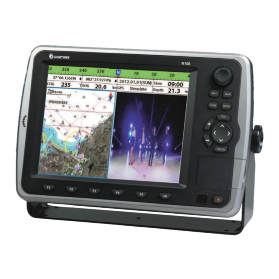
1-2 Specification 1 Introduction [NF100] GENERAL 1-1 General Information Category Detail 235mm(H) x 349mm(W) x 90mm(D) Size The chart plotter is a precision-crafted GPS Display 10.4 inch, TFT color, 800X600 pixel chart Plotter with high-performance receiver • NAVTEX Supply Voltage... -
Page 6: Components
General Category Detail 235mm(H) x 349mm(W) x 90mm(D) Size Part Number List Display 10.4 inch, TFT color, 800X600 pixel NF100 N100 Supply Voltage 11 ~ 36 V DC Supply current 24V (Equipment only) Display NF100-K N100-K Maximum LCD Brightness 750mA... -
Page 7: Getting Started
2-2 Buttons 2 Getting Started [FRONT] 2-1 Installation The chart plotter is supplied with bracket and flush mounting kit. You can choose a method of installation according to your preference. 2-1-1 Bracket Mounting Encoder – Used to select up, down, left, right Find the appropriate place to install considering GPS Chart plotter’s weight and user convenience. - Page 8 [REM-350] ① ② ④ ⑥ ③ ⑤ ⑦ ⑧ ① Press F1 once goes to Plotter à press it consecutively and will show Plotter and low frequencyà press again and will show plotter and high frequencyà press again and will show plotter and dual frequencyà...
-
Page 9: Navionics Sd Card, Usb
2-5 Simulation 2-3 NAVIONICS SD Card, USB Simulation Mode is great for practicing the actual use of a product when the satellites This section explains how to insert and signals and internal alarms are not available. Turn off the simulation remove the NAVIONICS SD Card and USB. -
Page 10: Compass
2-7 Compass 2-8 Multi Window Display The chart plotter computes compass direction To turn the compass off and on Chart plotter can display up to four windows Changing window size from the constellation of GPS satellites. It is 1 Press and select Data bar. -
Page 11: User Line Drawing
2-9 User Line Drawing Active window The user may draw a line or set the Mark Up to 999 Lines, marks, characters could be If more than one windows are displayed, the active window has blue border around it. If you using this function. -
Page 12: General Operation
3 General Operation 3-3 Main window To display the one window from the main page, press and select function you wish to 3-1 Power on and off show. Power on Power off Press and hold until the display shows Press and hold . -
Page 13: Chart
Echo Sounder Chart Video 3-4 Chart Chart window shows all the navigational relevant data of S-MAP and NAVIONICS (buoys, lights, cables, depth sounding, marinas, tide station) 3-4-1 Chart Window To go to the Chart window: ① Data bar. You may change the data Press and select Chart icon. -
Page 14: Latitude And Longitude
3-4-2 Latitude and Longitude Latitude and longitude coordinates define 3-4-5 SAMYUNG Map Search the position on earth and can be displayed on Latitude: The angular distance north or south data bar. from the equator of a point on the earth’s This function is available when it has been In the data bar, vessel’s position will show as surface, measured on the meridian of the... -
Page 15: Going To A Waypoint Or To A Point On The Chart
3-4-10 Distance and bearing calculator Saving route The unit can show the bearing and the length 3-4-8 Going to a waypoint or to a point on the chart of leg and the total distance of legs. 1 Set all the legs then press and select Setting Legs Save. -
Page 16: Setting Tracks In The Chart Window
3-4-14 3D MAP Pressing the shows the menu to allow you to set 3D map 3-4-13 Setting Tracks in the chart window To set the tracks on chart window, press and Enlarge the range: If you raise the value of hold (Refer to 4-5 Track Setting) range, the value gets displayed exaggerated. -
Page 17: Sonar
3-5-1 Option Movie option When you press , option displays 3-6 Sonar External video option Open: Opens the file from SD card and USB.(shortcut: When you press option displays. It is possible to use the Sonar function when it is connected to the transducer. Play: Play the file (shortcut: Input: You may select from composite-1, Follow the following steps to activate the Sonar function. -
Page 18: Single Or Dual Frequency Fish Finding
3-6-3 Single or Dual Frequency Fish finding [When the set depth is too low] [When the set depth is too high] Sonar frequencies The display is useful for comparing the same The unit has dual frequency, 200kHz and picture with two different frequencies. 50kHz to detect various bottom conditions. -
Page 19: Sonar Window Display
3-6-8 Split zoom and Full Screen zoom 3-6-6 Sonar window display Split zoom Bottom lock Split zoom mode expands selected area of If Bottom lock is on, the zoom depth (the Five sonar display windows are available and Split A-Scope: Display Sonar history and the single frequency by VRM(Variable Range depth of the zoom section) is adjusted each display window has unique... -
Page 20: Split 50/200
3-6-10 Split 50/200 3-7 Highway The 50 kHz display appears on the left and The Highway window shows a 3D view of the 200 kHz appears on the right. This dual the vessel traveling through the water when frequency display is very useful for navigating to a destination point. -
Page 21: Waypoints
1 Move the cursor to the waypoint you 1 Move cursor key to highlight a waypoint you want want to edit. 3-9 Waypoints to edit. (If you move the cursor on the 2 Press and select Edit. waypoint correctly, waypoint information 3 Edit waypoint data as you need and press A waypoint is a particular location on a will be displayed at the bottom left) -
Page 22: Sort Waypoints
3-10 Routes A trip from one place to another often involves several course changes, requiring a series of waypoints which you navigate to, one after another. The sequence of 3-9-6 Sort Waypoints 3-9-7 Deleting all waypoints waypoints leading to the final destination is called a route. -
Page 23: Managing A Route From The Route Window
3-10-2 Managing a route from the route window 3-11 Satellites Creating a rout from the route window Deleting a waypoint in the waypoint list 1 To go to the Route window, press 1 Highlight a waypoint you want to delete in and select the Route icon the waypoint list. -
Page 24: Tides
3-12 Tides 3-13 AIS The Tides window is useful for boaters that The tides window shows data for the AIS is an Automatic Identification System for identification and localization of boat. AIS provide chosen date are concerned about the height of the water a means for boats to exchange and share boat data including identification, position, course, or by fisherman that wish to know the tide etc. -
Page 25: Dsc
3-14 DSC This feature requires connection to optional DSC VHF radio. [AIS Vessel Information -1] [AIS Vessel List] DSC window shows the distress and poll information received from other vessel through DSC VHF radio. 1 Press and Hold , then select the system configuration. 2 Select the optional components and select DSC 3 Press , press... -
Page 26: Poll
3-14-2 Poll Poll Deleting a poll 3-15 Navtex A compatible radio with the unit can request 1 Highlight a received distress call you want the position of other DSC VHF radio equipped to delete. NAVTEX is an international automated direct Deleting a message and select Delete. -
Page 27: Settings
4 Settings 4-2 Chart settings To go to the chart settings: The system menu mainly consists of settings which do not require frequent adjustment. 1 Press and hold To go to system menu, press and hold then select the icon you want. 2 Select the chart icon. -
Page 28: Rotation
Projected course: Display the Projected 4-2-1 Rotation on or off 4-2-7 Map shift course in given set time. Restricted Area: Turns the displaying of Three types of display presentations are Sometimes current position of own ship does CDI scale: Set CDI (Course Deviation Restricted area on or off provided. - Page 29 4-3 Sonar settings 4-4 GPS Settings Sonar feature requires a connection to depth transducer. To go to the GPS settings: To go to the Sonar settings: 1 Press and hold 1 Press and hold 2 Select the GPS icon. 2 Select the sonar icon. 4-3-1 Frequency Fish sensitivity You can select a sonar frequency among 200...
- Page 30 4-6 Memory Settings 4-5 Track & Log Settings To go to the memory settings: 1 Press and hold To go to the tracking and long settings: 1 Press and hold 2 Select the Memory icon. 2 Select the track & log icon. A user card is an option SD card which you need to purchase additionally.
- Page 31 4-6-4 Format 4-6-5 Screen Snap Shot 4-7-1 Display Filter Erase all data in the user card. Format the To take the snap shot of current screen, press Filter by speed : Vessels with speed below There are a couple of methods to filter AIS user card before using it.
- Page 32 4-9 Other settings 4-8 Alarm Settings then select Others: Press long Press long then select Alarms: A warning message with beep sound is displayed when an alarm condition is met by user setting. Press to clear the alarm. However, the alarm will be displayed again when the alarm condition occurs again.
-
Page 33: Optional Parts
4-9-1 Simulate Select the Port(NMEA0183-Por1, Simulate :Turn the simulate mode on or off. NMEA0183-Port2, NMEA2000) and 5 CONNECTIONS Mode : See 2-5 Simulate Mode. Transmission speed and select the Speed : The simulated boat speed to use. demanded output information. Course : The simulated course over ground. - Page 34 [DATA] Number Description of pin [Number of Connector Pin] DGPS_OUT +12V +12V GND CAN_H CAN_L CAN_GND DGPS_GND DGPS_IN [MEDIA] Number Description of pin +12V_GND AUDIO_GND AUDIO_IN_R AUDIO_OUT_L AUDIO_GND ETHERNET MEDIA DATA SONAR REMOTE POWER +12V VIDEO_GND [POWER & DATA] VIDEO_GND VIDEO_IN1 Number of Pin Color...
-
Page 35: Power Supply & Data Cable
5-5 GPS ANTENNA 5-2 CONNECTION Selection of antenna GPS Chart plotter has the connection device to connect with the NMEA equipment like power Install one of the GPS antennas from below. supply, GPS antenna, AIS receiver, auto pilot device and digital equipment. 5-5-1 External antenna *Warning: Check that the power supply cable does not get connected to the REMOTE Connector or the DATA connector. -
Page 36: Data
connecting other NMEA equipment. the NMEA data, select the NMEA output and 5-7-1 DGPS/NMEA ANTENNA 5-7-2 NMEA2000 • The equipment can receive information on be certain about NMEA data. You can connect several equipment to one NMEA 2000 regulation has been implemented paddlewheel, speed, temperature, depth of external GPS by receiving the GPS data in the for communication between navigational... -
Page 37: Media
5-8 MEDIA Menu Tree You may use CCTV, S-VIDEO, external speaker, microphone Main menu 1. Introduction 1-1 General Information 1-2 Specification Pin No. Details 1-3 Components VIDEO_GND 1-4 Optional accessories VIDEO_GND VIDEO_Y 2. Getting Started 2-1 Installation 2-1-1 Bracket mounting VIDEO_C 2-2 Button S-VIDEO PIN MAP... - Page 38 4-3 Sonar setting 4-3-1 Frequency 3-7 Highway 4-3-2 Palette 3-8 Data 4-3-3 Scroll Speed 3-9 Waypoints 3-9-1 Creating new waypoint 4-3-4 Font Size 3-9-2 Change the waypoint 4-3-5 Fish 3-9-3 Edit the waypoint 4-3-6 Advance setting 3-9-4 Delete waypoint 4-3-7 Restore default 3-9-5 Find waypoint 3-9-6 Sort Waypoint 4-4 GPS Setting...
- Page 39 System Maintenance In order to maintain the full function of equipment, regular maintenance and repair is 4-9 Other setting 4-9-1 simulation compulsory. This includes regular checkup, software upgrade, and should at least include 4-9-2 Waypoint the below chart. 4-9-3 GPS Item Contents 4-9-4 Units...
- Page 40 Diagnosis The chart explains the general symptoms of breakdown and solutions to it. N100/NF100 Installation User should not disassemble equipment. The attempt may degrade the function of equipment or shorten the life of it. Therefore you take it to the professional engineer (A/S 1.
- Page 41 1 YEAR WARRANTY Thank you for purchasing an SAMYUNG ENC product. This product has been thoroughly checked and is covered by the Samyung ENC’s warranty for defects in materials and workmanship under normal use from the date of purchase. This warranty provides for the free repair or replacement of defective parts from our Samyung ENC authorized dealer.
- Page 42 User Guide User Guide...
- Page 43 User Guide...
Need help?
Do you have a question about the NF100 and is the answer not in the manual?
Questions and answers