Table of Contents
Advertisement
Quick Links
Advertisement
Table of Contents

Subscribe to Our Youtube Channel
Related Manuals for Samyung ENC N100


Summary of Contents for Samyung ENC N100
- Page 2 User manual...
- Page 3 Safety instructions This device's electronic chart system (ECS) is developed for the navigational aid only and chart itself does not obtain any approvals; has not been certified from the government authorities. If operator needs safe navigation then must use an official chart that has been approved by government agencies;...
-
Page 4: Table Of Contents
1 Introduction ..................... 7 1-1 General information .................... 7 1-2 specification ..................... 8 2 Getting started ..........10 2-1-1 Bracket Mounting ..............10 2-2 Button ......................11 2-3 SD card, USB ....................14 2-4 Power on and off ....................15 2-5 Brightness, night mode and Background ............... - Page 5 3-3-5-6 pulse power ................31 3-3-5-7 noise filter ................31 3-3-5-8 restore default ............... 31 3-4 AIS ......................... 32 3-4-1 AIS Display ................32 3-4-2 AIS Vessel information ............... 32 3-4-3 Sorting Vessel ................33 3-4-4 Display filters ................34 3-4-5 Display options .................
- Page 6 DGPS input ..................48 Course Filter ..................48 Occasional waves and wind at sea affect the boat course. In order to have stable boat course, the unit calculates these factors to give the value of stable course information..............48 Lat/Lon d.p’s ..................
-
Page 7: Introduction
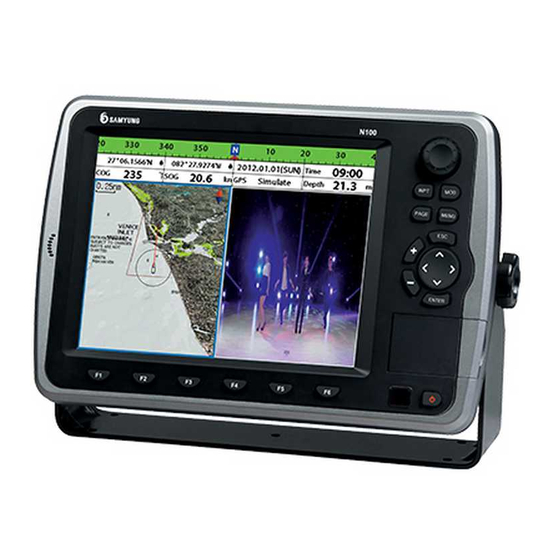
1 Introduction 1-1 General information The chart plotter is a precision-crafted GPS chart Plotter with high-performance • NAVTEX receiver for the Global Positioning System • VIDEO constellation of satellites, providing • AIS RECEIVER precise location data with a host of •... -
Page 8: Specification
1-2 specification NF100A User manual... - Page 9 N100A...
-
Page 10: Getting Started
2 Getting started The chart plotter is supplied with bracket and flush mounting kit. You can choose a method of installation according to your preference. 2-1-1 Bracket Mounting Find the appropriate place to install considering GPS Chart plotter’s weight and user convenience. -
Page 11: Button
2-2 Button [Front] Encoder – When pressed briefly - cursor on/off When turning the button (fishfinder) control of depth range (chart, chart/fishfinder) chart display Zoom/zoom out – create waypoint. Center – position of cursor is located on the center of screen. (if there’s no cursor) Position of vessel is located on the center Route... - Page 12 ① ④ ② ⑥ ③ ⑤ ⑦ ⑧ ① ① Press F1 once goes to Plotter a press it consecutively and will show Plotter and low frequency press again and will show plotter and high frequency press again and will show plotter and dual frequency press again for low frequency a high frequency dual frequency then it will go back to Plotter ②...
- Page 13 [REM-330-E] fishfinder low/high Power frequency Power ON/OFF Slection of low /high frequency Depth range Gain/attenuation MOB Display “Man over board” Convert plotter and fishfinder screen Enter Select option or Convert Converting N/S, W/E, +/- 90 confirm the selection N/S, W/E, Waypoint skipping, Inverse route and navigation...
-
Page 14: Sd Card, Usb
2-3 SD card, USB This section explains how to insert and remove the NAVIONICS SD Card and USB. Inserting SD Card 1 You have two slots for SD card as shown in ①, when you insert to the left slot, face the label to left as shown in ③... -
Page 15: Power On And Off
2-4 Power on and off Power on Power off Press and hold until the display shows Press and hold . It will start a count the start up page. Press to accept the down. If you do not release the button warning screen. -
Page 16: Menu Configuration
2-6 Menu configuration 1.navigation 1. Go to cursor 2. Chart 1. Chart Info naNavigatio 2. Mark 2. Distance measure 3. Track 3. Search 4. Waypoint 4. Setting 5. Route 6. User Line 7. Navigation Record 3. Sonar 1. Display Mode 4. - Page 17 7. screen 1. Map 8. Screen 1. Add display mode setup 2. Fishfinder 2. Remove display 3. Video 3. Switching display 4. Highway 4. Divide display 5. Gauge 5. Capture 6. Satellite 6. Load Information 7. Tides 7. Gauge Layout 8.
-
Page 18: Function
3 Function 3-1 Navigation 3-1-1 Go to cursor Determing the waypoint by locating the Reconfigure for course breakaway custor. Change the waypoint. This menu will be While the cursor is activated appeared once the waypoint is created 1 Select 1 Select. 2 Select Navigation and select Go to Cursor 2 Select Nagivation and Select Go to Cursor. -
Page 19: Track
1 Select and select Navigation 2 Select Mark. Memory 3 Select how to delete Manage mark datebase Delete all – Delete all Marks Save – Select the disk to save mark Delete by mark – Delete the chosen mark. information. Then enter filename and Delete by color –... -
Page 20: Waypoints
3-1-4 Waypoints A waypoint is a particular location on a Delete waypoint voyage whether it is a starting, intermediate 1 Select or destination point. A waypoint is the 2 Select navigation and select waypoint. simplest piece of information your 3 Select Delete and select waypoint to be equipment requires to get you to a deleted destination. -
Page 21: Route
3-1-5 Route A trip from one place to another often Insert the waypoint during the route involves several course changes, requiring a creation series of waypoints which you navigate to, 1 If you want to insert a waypoint between one after another. The sequence of waypoints which will be just after the one waypoints leading to the final destination is you want to insert. -
Page 22: User Line
3-1-6 User Line The user may draw a line or set the Mark using this function. User Line Drawing 1 Press and Select goto. You can insert 999 line, mark and letter. 2 Select User Line 3 Select User line drawing. Delete all line 4 Press F1 and move cursor as much as All lines on the screen is deleted... -
Page 23: Chart
3-2 Chart 3-2-1 Distance and bearing calculator The unit can show the bearing and the length of leg and the total distance of legs. Setting Legs 1 In the chart window, press and select Distance. Information is displayed on window showing bearing/leg distance/total distance at the bottom left side of display. 2 Move the cursor to the starting point of the first leg and press 3 Repeat step 2 for more legs 4 Press... -
Page 24: General
When you select other Map datum different 3-2-3-1 Rotation from WGS84, latitude and longitude will be Three types of display presentations are different from WGS84’S coordinates and this provided. The default is heading up. might confuse other device such as VHF radio North up: North is at the top of the display. - Page 25 major chart system and this option allows you to select a map datum. The default datum is WGS84.
-
Page 26: Sonar
3-3 Sonar 3-3-1 scroll mode Five sonar display windows are available Split A-scope: Display Sonar history and and each display window has unique echo strength. (see section 3-6-6-5) characteristics. Select a display window Spited screen ratio can be set depending on your needs. The default 1 Press and select Sonar and display is No split. - Page 27 Split zoom and full screen zoom Bottom lock Split zoom mode expands selected area of If Bottom lock is on, the zoom depth (the the single frequency by VRM(Variable Range depth of the zoom section) is adjusted Mark). The left side displays zoomed section automatically so that the bottom is always of current sonar record.
- Page 28 split(50/200) The 50 kHz display appears on the left and the 200 kHz appears on the right. This dual frequency display is very useful for comparing the same scanning with two different frequencies. Split A-Scope This display shows echoes at each transmission with amplitudes and colors proportional to their intensities;...
-
Page 29: Single Or Dual Frequency Fish Fishing
3-3-2 Single or dual frequency fish fishing Sonar frequencies The display is useful for comparing the The unit has dual frequency, 200kHz and same picture with two different 50kHz to detect various bottom conditions. frequencies. 1 Press , select Frequency. 2 Select one frequency High frequency (200kHz ) The higher ultrasonic signal, the better is... -
Page 30: Gain
3-3-4 Gain Gain Mode To change a mode, You may choose from two modes. 1 Press , select Gain. • Auto mode: This function is used while 2 Select a mode. vessel is moving. The unit adjusts the 3 If you select a Manual mode, adjust each setting of bottom of water according to frequency gain value by pressing the environment automatically... -
Page 31: Sonar Setting
3-3-5 Sonar setting Sonar feature requires a connection to depth transducer. To go to the sonar setting 1 Press and hold 2 Select the sonar icon. 3-3-5-1 scroll speed 3-3-5-4 pulse length . You can set the scroll speed which You can select specific pulse length of transducer. -
Page 32: Ais
3-4 AIS AIS is an Automatic Identification System for identification and localization of boat. AIS provide a means for boats to exchange and share boat data including identification, position, course, etc. This information can be displayed on the screen of you unit. AIS is intended to assist you to monitor other boats movements to improve safety and prevent collision. -
Page 33: Sorting Vessel
[AIS Vessel Information -1] [AIS Vessel List] [AIS Vessel Information -2] [AIS Vessel Safety message] 3-4-3 Sorting Vessel Sort up the AIS Vessel List by the selected condition 1. Press , select Sort by. 2 Select one of the options... -
Page 34: Display Filters
3-4-4 Display filters Filter by Type The type of vessel which is selected will not be displayed on the chart. Filter by distance Vessels outside the radius of selected distance from own ship is filtered. Filter by speed Vessels with speed below the set value are filtered. -
Page 35: Multimedia
3-5 Multimedia You may use the media cable to connect with CCTV, S-VIDEO or download the files from SD Card, USB to play it on the video function. 3-5-1 Video Video Set Caption: When you tick the box, the subtitle displays for the playing video file. Repeat: The file repeats itself when it ends. -
Page 36: Alarms
3-6 Alarms Press and select Alarms: A warning message with beep sound is displayed when an alarm condition is met by user setting. Press to clear the alarm. However, the alarm will be displayed again when the alarm condition occurs again. The unit provides alarms for various functions. User manual... -
Page 37: Fish
3-6-1 Fish 3-6-8 AIS Trigger an alarm when the wave received Dangerous Vessel from the transducer is same as fish value. When this option is selected an alarm will 3-6-2 Deep activate. Even this option is not selected; Trigger an alarm when the depth value dangerous vessels will still be on the chart. -
Page 38: Screen Modes
3-7 Screen Modes Press and select screen mode to apply Caution 1 Each options are available depends on installed equipment and additional option sensor. 3-7-1 Chart Go to Chart screen. ① Data bar. You may change the data 1 Press and select Screen Mode. -
Page 39: Sonar
3-7-2 Sonar ① Depth ① ② Single Fish: Fish symbol with depth ③ School of fish ② ④ Depth line ⑧ ② ⑤ Bottom: Hard bottoms such as rock and coral shown as wide bands. Soft ⑨ ③ bottoms such as mud, weed and sand ④... -
Page 40: Data
3-7-5 Data The Data window displays all the information you need during navigation such as water, engine, fuel related information, etc. 3-7-6 Satellite Acquiring GPS signals Press to display GPS signal When the unit is first turned on it needs information from GPS satellite in some time for the GPS signal acquiring. -
Page 41: Tides
3-7-7 Tides The Tides screen is useful for boaters who The tides screen shows data for the chosen are concerned about the height of the date. ⑤ water or fisherman who wish to know the tide and moon phase of a specific date. ①... -
Page 42: Screen Setup
3-8 Screen Setup Chartplotter display split 3-8-2 Remove screens at once. 1 Press and select Screen Setup. 2 Select Remove. 3 Choose the screen position to remove. 3-8-1 Add 1 Press and select Screen Setup. 3-8-3 Replace 2 Select Add. 1 Press and select Screen Setup. - Page 43 3-8-5 Save You can save the composition of screen. 1 Press and select Screen Setup. 2 Select Save. 3 Select the slot to save. If you choose the one in use it will be removed and covered with new composition. 3-8-6 Screen Load Load the saved screen composition.
- Page 44 Data bar set up Location of data bar Setting the data displayed in the bar 1 Press and select Screen setup. 1 Press and select Data bar. 2 select data bar. 2 Select Data bar then Data bar setup 3 select data bar. 3 Move the cursor key to select the data 4 select the location field you wish to change and press...
-
Page 45: Others
3-9 Others... -
Page 46: Simulation
3-9-1 Simulation 3-9-6 Memory Simulation: start/stop simulation mode format: This function will allow the user to Mode: • standard: user may adjust speed, delete all data from card. The user must course, route for simulation format the card before the use. •... -
Page 47: System
3-10 System... -
Page 48: Language Setting
3-10-1 Language setting Magnetic variation You may select the language including This option compensates the difference English between true north magnetic north. We do not recommend changing 3-10-2 Map Setting the setting if not well aware of the You may select between Samyung Map function. -
Page 49: Connections
5 CONNECTIONS Accurate installation highly affects the performance of this equipment. You must read the manual on installation, antenna and other equipment information before installation process. For information on the additional equipment, contact SAMYUNGENC and check. 5-1 OPTIONAL PART Optional sense and equipment •... - Page 50 [Number of Connector pin] ETHERNET MEDIA DATA SONAR REMOTE POWER [POWER & DATA] Number of Pin Color Description BLACK Enter -POWER BROWN WHITE NMEA0183 output BLUE NMEA0183 input +POWER input, 11 to 36V DC ORANGE YELLOW NMEA0183 GND GREEN output the external alarm, maximum 30V DC 200mA [SONAR] [REMOTE]...
-
Page 51: Connection
5-2 CONNECTION GPS Chart plotter has the connection device to connect with the NMEA equipment like power supply, GPS antenna, AIS receiver, auto pilot device and digital equipment. *Warning: Check that the power supply cable does not get connected to the REMOTE Connector or the DATA connector. -
Page 52: Gps Antenna
5-5 GPS ANTENNA Selection of antenna Install one of the GPS antennas from below. 5-5-1 External antenna Internal GPS antenna’s reception is affected by the place where equipment gets installed. If the internal GPS antenna’s reception is poor, to enhance the GPS signal, you may connect the external GPS antenna. -
Page 53: Nmea 0183
5-6 NMEA 0183 GPS chart plotter can be connected to the • DSC VHF Radio external equipment that uses NMEA0183 as • GPS antenna(NMEA 0183) below. • NAVTEX • AIS RECEIVER PIN No. : 4 (Data in) INPUT PIN No. : 3 (Data out) OUTPUT NMEA 0183 PIN No. -
Page 54: Dgps/Nmea Antenna
5-7-1 DGPS/NMEA ANTENNA 5-7-2 NMEA2000 You can connect several equipment to one NMEA 2000 regulation has been external GPS by receiving the GPS data in implemented for communication between the form of NMEA from external navigational map, navigation, engine, tank equipment. -
Page 55: Media
5-8 MEDIA You may use CCTV, S-VIDEO, external speaker, microphone Pin No. Details VIDEO_GND VIDEO_GND VIDEO_Y VIDEO_C S-VIDEO PIN MAP S-VIDEO CCTV MEDIA POWER +12V Cable MICROPHONE Extnl. Speaker... -
Page 56: Set Up And Test
5-9 Set up and Test 1 You should place the rubber cover to the connector not in use at the back of the display unit. All connector must be connected to the plug and display unit must be installed at the right place. 2 If this equipment is set with bracket mounting, to optimize the view of screen, adjust the slope and rotate it and tighten the knob. -
Page 57: System Maintenance
System Maintenance In order to maintain the full function of equipment, regular maintenance and repair is compulsory. This includes regular checkup, software upgrade, and should at least include the below chart. Item Contents Connector and Check the connectors and terminals on the back of the equipment are terminal normally connected. - Page 58 Diagnosis The chart explains the general symptoms of breakdown and solutions to it. User should not disassemble equipment. The attempt may degrade the function of equipment or shorten the life of it. Therefore you take it to the professional engineer (A/S Center) AS Center ☏...
- Page 59 N100A/NF100A Installation 1. If not connected to AIS, Autopilot, DGPS (Interconnect to the Power Cable 8P) POWER CABLE (8P) GNB-400S 3. TX(WHITE) RX(BLUE) 4. RX(BLUE) TX(YELLOW) 7. GND(YELLOW) GND(WHITE) POWER EXT Power+RED DC+10~36V EXT Power-BLACK 2. When two equipment AIS and Autopilot are connected (Interconnect to the Data Connector LTW 8P) DATA CONNECTOR LTW(8P) GNB-400S...
- Page 60 This warranty provides for the free repair or replacement of defective parts from our Samyung ENC authorized dealer. In the event that your SAMYUNG ENC product needs service, please return your SAMYUNG ENC product at your expense (shipping and insurance) to your Samyung ENC distributor or SAMYUNG ENC authorized Service Centres.
Need help?
Do you have a question about the N100 and is the answer not in the manual?
Questions and answers
не видит карту
The Samyung ENC N100 may not recognize the card due to incorrect insertion. Ensure the NAVIONICS SD card is inserted correctly:
- For the left slot, face the label to the left.
- For the right slot, face the label to the right.
Additionally, if the unit is in simulation mode, it may ignore signals. Turn off simulation mode when using the card.
This answer is automatically generated