
Related Manuals for Case WX148


Summary of Contents for Case WX148
- Page 1 WX148 Wheeled Excavator SERVICE MANUAL Part number 47500167 English January 2013 Copyright © 2013 CNH Europe Holding S.A. All Rights Reserved.
- Page 2 SERVICE MANUAL WX148 47500167A 31/01/2013 Find manuals at http://best-manuals.com/search?&s=CASE-47500167...
- Page 3 [33.110] Parking brake or parking lock ............33.1 47500167A 31/01/2013 Find manuals at http://best-manuals.com/search?&s=CASE-47500167...
- Page 4 [41.216] Cylinders ................41.4 Wheels ..................44 47500167A 31/01/2013 Find manuals at http://best-manuals.com/search?&s=CASE-47500167...
- Page 5 [86.110] Dozer blade ............... . 86.1 47500167A 31/01/2013 Find manuals at http://best-manuals.com/search?&s=CASE-47500167...
- Page 6 [90.150] Cab ................. 90.3 47500167A 31/01/2013 Find manuals at http://best-manuals.com/search?&s=CASE-47500167...
- Page 7 47500167A 31/01/2013 Find manuals at http://best-manuals.com/search?&s=CASE-47500167...
- Page 8 INTRODUCTION 47500167A 31/01/2013 Find manuals at http://best-manuals.com/search?&s=CASE-47500167...
-
Page 9: Table Of Contents
Product identification ................41 47500167A 31/01/2013 Find manuals at http://best-manuals.com/search?&s=CASE-47500167... -
Page 10: Safety Rules
NOTE: It emphasizes and underlines to the operator the correct technique or correct procedure to follow. ATTENTION: It warns the operator of a possible hazard of machine damage in case he does not follow a determined procedure. Your safety and that of people around you depends on you. -
Page 11: Note To The Owner
INTRODUCTION Note to the Owner The wheeled excavators are operation hydraulic ma- chines. They essentially consist in a wheeled undercarriage on which a slewing bearing is mounted, which is coupled to the upper frame. The upper frame supports the front attachment, the en- gine, the hydraulic components, the cab, the fuel tank and the counterweight. - Page 12 INTRODUCTION NOTICE: It is absolutely forbidden to tamper and/or change the setting of any of the hydraulic system valves to avoid damaging machine components with consequent risks to personal safety. Instructions concerning safety, operation and maintenance have been developed to permit safe service and operation of this machine.
-
Page 13: Personal Safety
INTRODUCTION Personal safety Carefully read this Manual before proceeding with main- tenance, repairs, refuelling or other machine operations. Repairs have to be carried out only by authorized and in- structed staff; specific precautions have to be taken when grinding, welding or when using mallets or heavy ham- mers. - Page 14 Do not refuel with the engine running, especially if hot, as this increases fire hazard in case of fuel spillage. Never attempt to check or adjust the belts when the en- gine is running.
- Page 15 INTRODUCTION Pay attention to rotary pieces and do not allow to anyone to approach to avoid becoming entangled. If hands, clothes or tools get caught in the fan blades or in the transmission belt, this can cause amputations, violent tears and generate condition of serious danger; for this reason avoid touching or to come close to all rotary or moving parts.
- Page 16 INTRODUCTION When hydraulic oil has been swallowed, avoid vomiting, but consult a doctor or go to a hospital. If an accident occurs, see a doctor familiar with this type of injury immediately. Any fluid penetrating the skin must be removed within few hours to avoid serious infections.
- Page 17 INTRODUCTION Hoses and tubes Always replace hoses and tubes if the cone end or the end connections on the hose are damaged. When installing a new hose, loosely connect each end and make sure the hose takes up the correct position be- fore tightening the connections.
- Page 18 INTRODUCTION Battery Batteries give off explosive gases. Never handle naked flames and unshielded light sources near batteries, never smoke. To prevent any risk of explosion, observe the following instructions: • When disconnecting the battery cables, always discon- nect the negative (-) cable first. •...
- Page 19 INTRODUCTION Flammable liquids When handling flammable liquids: • Do not smoke. • Keep away from unshielded light sources and naked flames. Fuels often have a low flash point and are readily ignited. Never attempt to extinguish burning liquids with water. Use: •...
- Page 20 INTRODUCTION Tyres Before inflating the tyres, always check the condition of rims and the outer condition of tyres to find out the pres- ence of dents, cuts, tears of reinforcement plies or other faults. Before inflating a tyre, make sure that there are no nearby persons, then position yourself at tread side.
- Page 21 INTRODUCTION Waste disposal Improperly disposing of waste can threaten the environ- ment. Each country has its own Regulations on this subject. It is therefore advisable to prepare suitable containers to collect and store momentarily all solid and fluid materials that must not be scattered in the environment to avoid pollution.
-
Page 22: Product Overview
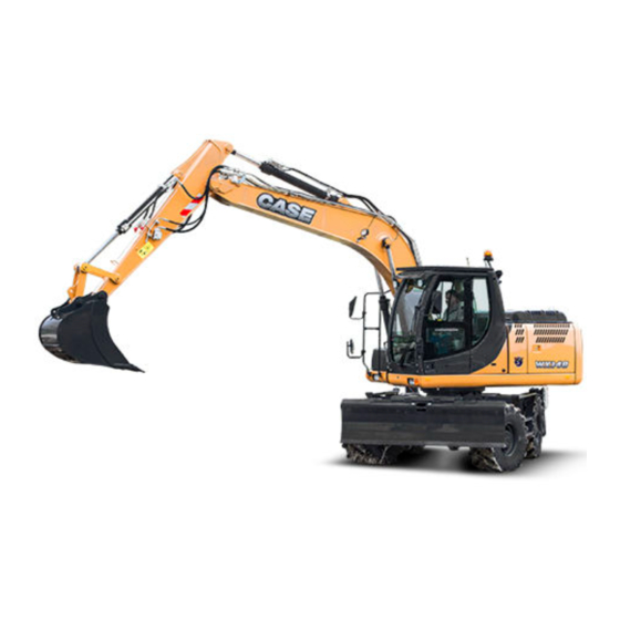
INTRODUCTION Product overview Main components (2-piece boom) - External view SMIL12WEX0294GB Bucket 11. Side doors Bucket cylinder 12. Rear stabilizers Dipper 13. Rear axle wheels Dipper cylinder 14. Cabin Second boom 15. Stairs - storage box Cylinder 16. Front axle wheels Boom cylinders 17. - Page 23 INTRODUCTION Main components (monoboom) - External view SMIL12WEX0295GB Bucket 10. Rear stabilizers Bucket cylinder 11. Rear axle wheels Dipper 12. Cabin Dipper cylinder 13. Stairs - storage box Boom 14. Front axle wheels Boom cylinder 15. Front blade Engine cover 16.
- Page 24 INTRODUCTION Upper structure main components - internal view SMIL12WEX0175GB Slewing bearing 11. Radiator assy Refueling pump box 12. Condenser + dryer (conditioning air system) Protection handrails 13. Batteries Main valve 14. Air filter Fuel tank 15. Pilot control assy Hydraulic oil tank 16.
- Page 25 INTRODUCTION Undercarriage main components TULI12WEX2029GB Front wheels Rear wheels Front blade Left stair Front axle locking cylinders 10. Front steering axle Right stair 11. Cardan shaft Swivel joint 12. Travel motor Electric rotor 13. Trasnmission 14. Rear rigid axle Rear stabilizers 47500167A 31/01/2013...
-
Page 26: Basic Instructions
INTRODUCTION Basic instructions Machine safety Before carrying out any service or repair work the machine must be secured as follows: Park the machine on a level and firm surface. Lower the working attachment to the ground. Lower the blade and the stabilizers to the ground. Lock the upper structure. -
Page 27: Dimension
INTRODUCTION Dimension Triple articulation version - transport dimensions SMIL12WEX0081EA Front blade and rear stabilizers Dipper 2100 2450 2950 2616 mm (103.0 in) 2707 mm (106.6 in) 3125 mm (123.0 in) 2616 mm (103.0 in) 2707 mm (106.6 in) 3050 mm (120.1 in) 2616 mm (103.0 in) 2707 mm (106.6 in) 3050 mm (120.1 in) - Page 28 INTRODUCTION SMIL12WEX0082EA Rear stabilizers Dipper 2100 2450 2950 2616 mm (103.0 in) 2707 mm (106.6 in) 3050 mm (120.1 in) 2616 mm (103.0 in) 2707 mm (106.6 in) 3050 mm (120.1 in) 2616 mm (103.0 in) 2707 mm (106.6 in) 3050 mm (120.1 in) 2543 mm (100.1 in) 2623 mm (103.3 in)
- Page 29 INTRODUCTION SMIL12WEX0083EA Rear blade Dipper 2100 2450 2950 2616 mm (103.0 in) 2707 mm (106.6 in) 3050 mm (120.1 in) 2616 mm (103.0 in) 2707 mm (106.6 in) 3050 mm (120.1 in) 2616 mm (103.0 in) 2707 mm (106.6 in) 3050 mm (120.1 in) 2543 mm (100.1 in) 2623 mm (103.3 in)
- Page 30 INTRODUCTION Monoboom version - transport dimension SMIL12WEX0084EA Front blade and rear stabilizers Dipper 2100 2450 2950 2884 mm (113.5 in) 3115 mm (122.6 in) 3601 mm (141.8 in) 2884 mm (113.5 in) 3102 mm (122.1 in) 3488 mm (137.3 in) 2884 mm (113.5 in) 3048 mm (120.0 in) 3457 mm (136.1 in)
- Page 31 INTRODUCTION SMIL12WEX0085EA Rear stabilizers Dipper 2100 2450 2950 2884 mm (113.5 in) 2972 mm (117.0 in) 3298 mm (129.8 in) 2884 mm (113.5 in) 2972 mm (117.0 in) 3298 mm (129.8 in) 2884 mm (113.5 in) 2972 mm (117.0 in) 3298 mm (129.8 in) 2830 mm (111.4 in) 2899 mm (114.1 in)
- Page 32 INTRODUCTION SMIL12WEX0086EA Rear blade Dipper 2100 2450 2950 2884 mm (113.5 in) 2972 mm (117.0 in) 3298 mm (129.8 in) 2884 mm (113.5 in) 2972 mm (117.0 in) 3298 mm (129.8 in) 2884 mm (113.5 in) 2972 mm (117.0 in) 3298 mm (129.8 in) 2830 mm (111.4 in) 2899 mm (114.1 in)
-
Page 33: Weight
INTRODUCTION Weight Triple articulate version - weights Front blade and rear Dipper Rear stabilizers Rear blade stabilizers 2100 mm (82.7 in) 16300 kg (35935.3 lb) 15750 kg (34722.8 lb) 15450 kg (34061.4 lb) 2450 mm (96.5 in) 16350 kg (36045.6 lb) 15800 kg (34833.0 lb) 15550 kg (34281.9 lb) 2950 mm (116.1 in) -
Page 34: General Specification
INTRODUCTION General specification Triple articulation version Dipper - 2100 mm (82.7 in) SMIL12WEX0078FA 1222 mm (48.1 in) Bucket radius Maximum digging height 9540 mm (375.6 in) Maximum loading height 7090 mm (279.1 in) Maximum digging depth 4770 mm (187.8 in) Maximum vertical wall digging depth 3580 mm (140.9 in) Maximum digging depth of cut for level bottom... - Page 35 INTRODUCTION Dipper - 2450 mm (96.5 in) SMIL12WEX0079FA 1222 mm (48.1 in) Bucket radius Maximum digging height 9830 mm (387.0 in) Maximum loading height 7370 mm (290.2 in) Maximum digging depth 5120 mm (201.6 in) Maximum vertical wall digging depth 3920 mm (154.3 in) Maximum digging depth of cut for level bottom 5000 mm (196.9 in)
- Page 36 INTRODUCTION Dipper - 2950 mm (116.1 in) SMIL12WEX0080FA 1222 mm (48.1 in) Bucket radius Maximum digging height 10260 mm (403.9 in) Maximum loading height 7810 mm (307.5 in) Maximum digging depth 5620 mm (221.3 in) Maximum vertical wall digging depth 4420 mm (174.0 in) Maximum digging depth of cut for level bottom 5520 mm (217.3 in)
- Page 37 INTRODUCTION Monoboom version Dipper - 2100 mm (82.7 in) SMIL12WEX0037FA Bucket radius 1222 mm (48.1 in) Maximum digging height 8520 mm (335.4 in) Maximum loading height 6130 mm (241.3 in) Maximum digging depth 4750 mm (187.0 in) Maximum vertical wall digging depth 3670 mm (144.5 in) Maximum digging depth of cut for level bottom 4500 mm (177.2 in)
- Page 38 INTRODUCTION Dipper - 2450 mm (96.5 in) SMIL12WEX0038FA 1222 mm (48.1 in) Bucket radius Maximum digging height 8730 mm (343.7 in) Maximum loading height 6330 mm (249.2 in) Maximum digging depth 5100 mm (200.8 in) Maximum vertical wall digging depth 4020 mm (158.3 in) Maximum digging depth of cut for level bottom 4890 mm (192.5 in)
- Page 39 INTRODUCTION Dipper - 2950 mm (116.1 in) SMIL12WEX0039FA 1222 mm (48.1 in) Bucket radius Maximum digging height 9070 mm (357.1 in) Maximum loading height 6660 mm (262.2 in) Maximum digging depth 5600 mm (220.5 in) Maximum vertical wall digging depth 4560 mm (179.5 in) Maximum digging depth of cut for level bottom 5420 mm (213.4 in)
-
Page 40: Capacities
INTRODUCTION Capacities Triple articulation version N00949 A (m) LD = 2.1 m LD = 2.45 m LD = 2.95 m NOTE: Value in the table are in ton. NOTE: 1 m (3.3 ft) 47500167A 31/01/2013... - Page 41 INTRODUCTION Monoboom version N00950 A (m) LD = 2.1 m LD = 2.45 m LD = 2.95 m NOTE: Value in the table are in ton. NOTE: 1 m (3.3 ft) 47500167A 31/01/2013...
-
Page 42: General Specification
INTRODUCTION General specification Hydraulic system The hydraulic system is supplied by 3 pumps, a main double pump, an independent pump for swinging and double gear pump for steering and brake, pilot hydraulic system and grab rotation. The engine and the pumps are monitored and controlled by the “Engine Speed Control”... - Page 43 INTRODUCTION Slewing The rotation function is actuated by a closed hydraulic circuit, driving a mechanical gearbox with built-in automatic static brake. Rotation speed 9 RPM Rotation torque ( SAE J1371) 36 N·m (26.6 lb ft) Slewing gearbox Model 705T2F/20.70 Total displacement 1159.2 cm³/rev (70.7 in³/rev) Hydraulic motor displacement 56 cm³/rev (3.4 in³/rev)
- Page 44 INTRODUCTION Travel Transmission with clutch pack. Maximum travel speed at job 5 km/h (3.1 mph) Maximum travel speed at job site (optional) 8 km/h (5.0 mph) Maximum travel speed on the road 20 km/h (12.4 mph) High speed on road (optional) 35 km/h (21.7 mph) Maximum drawbar pull (field) 92 kN (20682.4 lb)
- Page 45 INTRODUCTION Brakes Service brake Wet, actives on all wheels. Parking brake Mechanical brake at springs actuation, active on transmission. Steering Turning circle diameter (with 10.00-20 twin tyres) 15 m (49.21 ft) Power steering Model OSPD 60/185 LS Displacement 60 - 185 cm³/rev (3.66 - 11.29 in³/rev) Maximum steering pressure 190 - 200 bar (2755.0 - 2900.0 psi) Shock valve adjustment...
- Page 46 INTRODUCTION Fuel system Tank capacity 190 l (50.2 US gal) Engine Type F4GE9484D*J601 Displacement 4.5 l (1.2 US gal) Operation Diesel, water-cooled with turbocharger Cylinders arrangement in line Valves per cylinders 104 mm (4.09 in) Bore Stroke 132 mm (5.20 in) Power 90 kW (122.4 Hp) at 2000 RPM Maximum torque...
-
Page 47: Consumables
INTRODUCTION Consumables Supply summarizing chart QUAN- MANUFACTURER INTERNATIONAL COMPONENT TO BE FILLED AKCELA TITY SPECIFICATIONS SPECIFICATIONS 5.5 - 12.5 No. 1 Engine Oil API Cl 4 Engine l (1.5 - 3.3 MS 1121 15W–40 ACEA E7 US gal) 4.2 l (1.1 Transaxle Fluid API GL 4 Swing gear... -
Page 48: Product Identification
INTRODUCTION Product identification IDENTIFICATION DATA SMILWEX0013FB Machine identification plate Engine identification plate Model and category (Hydraulic Excavator) Engine type Machine serial number Engine emission stage approval number Nominal Power Engine serial number Unladen Mass Year of Manufacture 47500167A 31/01/2013... - Page 49 The ROPS label of homologation (2) is localized in the cab near the cab interior lighting. In the case of work where there is a risk of frontal impact where object could penetrate the cab, a front guard may be installed.
- Page 50 SERVICE MANUAL Engine WX TIER 3 47500167A 31/01/2013...
- Page 51 This as a preview PDF file from best-manuals.com Download full PDF manual at best-manuals.com...
Need help?
Do you have a question about the WX148 and is the answer not in the manual?
Questions and answers