
Subscribe to Our Youtube Channel
Related Manuals for Sawmaster M1030


Summary of Contents for Sawmaster M1030
- Page 1 M1030/M1036 Wet tile saw Owner’s Manual Keep for your records ATTENTION! Read safety and operating instructions carefully before operating the saw for the fi rst time. Retain manual for future reference.
-
Page 3: Table Of Contents
Contents Table of Contents Do’s & Don’ts for Blades Wet Cut Blades Safety Precautions Dry Cut Blades Saw Maintenance Features General Rules Specifications Water Pump Maintenance Health Warning Troubleshooting Unpacking Notes Set Up Replacement Parts List Saw Stand Assembly Warranty Folding Built-in Legs Deploying Built-in Legs How To Order... -
Page 4: Safety Precautions
M1036 • Owner’s Manual Safety Precautions L. A visual check of the machine must be made at least once a shift to ensure that visible damages or faults are recognized. Any changes (including changes in the performance or behavior of the machine) must be reported to the supervisor. -
Page 5: Features
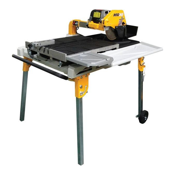
Height: 23-in 2 HP 30-in, Length: 45-in 10-in blade for 115 V/ 60 Hz, Diagonally cut Width: 34.5-in 2.4-in 128 lbs M1030 5⁄8-in arbors 3200 RPM 20-in tile Height: 23-in * Dimensions do not include extension tables and drip trays. -
Page 6: Health Warning
M1036 • Owner’s Manual Health Warning Set Up Some dust created by power sanding, sawing, grinding, See included SUPPLEMENTARY UNPACKING AND ASSEMBLY INSTRUCTIONAL BOOKLET for more details. drilling, and other construction activities contain chemicals known to cause cancer, birth defects or other reproductive harm. -
Page 7: Saw Stand Assembly
Saw Stand Use WARNING: The following steps should be done Table lock on a stable dry flat surface. WARNING: Lock the table before proceeding to prevent damage or bodily harm from sudden movement of the table. FOLDING BUILT-IN LEGS It is recommended that adjusting the folding leg be done by at least two people. -
Page 8: Preparation For Use
M1036 • Owner’s Manual Preparation for Use BLADE INSTALLATION Turn the silver knob on the inner blade guard counterclockwise until it pops out to unlock the blade guard. (see figure 3) Slide the outer blade guard horizontally across the inner blade guard towards the plunge handle. The tab at the rear of the blade guard must clear the enclosing slot. -
Page 9: Water Pump Usage Options
WATER PUMP USAGE OPTIONS Top water tray (rear section, closest to motor) Top water tray (front section) fi gure 5 Option 1. Water pump can be placed in the top water tray (A). (see figure 5) Only the top water tray would need water, but care must be taken to not over fill the tray or water will spill out from the over flow hole on the tray. -
Page 10: Operating The Saw
M1036 • Owner’s Manual Operating The Saw Turn on the saw. During the cut operation, the user must use both hands to hold the tile in place while also apply even force to push the table forward. Do not force feed the blade for best cut results. -
Page 11: Cutting Depth
CUTTING DEPTH USING THE CUTTING TABLE The recommended cutting depth is 1/4-in below the cutting The ruler guide has inches marked along the top to allow table surface. To adjust the depth raise/lower the blade by convenient measurements and to promote precision cuts. loosening the depth adjustment knob and use the plunge (see figure 10) With the side extension table installed, the handle to adjust the blade depth as necessary. -
Page 12: Performing Miter Cuts
M1036 • Owner’s Manual PERFORMING MITER CUTS Position the tile to be cut in the position that when the blade engages it, it will result in the desired cut. Since this time the cut is angled, place the guide’s attachment’s flat side such that it sits flush against the material. -
Page 13: Electrical Specification
Electrical Specifications Post Power and error indicator M1030/M1036 Power 2 HP olts 115 V 15 A Amps Blade Shaft RPM 2800 RPM Cycle 60 Hz Phase EXTENSION CORD CHART Wire Gauge Length of Cord fi gure 14 No. 12 25’... -
Page 14: Do's & Don'ts For Blades
M1036 • Owner’s Manual Do’s & Don’ts For Blades Wet Cut Blades DO'S DON'TS Inspect blades daily for cracks Do not operate the saw without • • or uneven wear. safety guards in position. Always use appropriate blade Do no operate the saw with •... -
Page 15: Saw Maintenance
Saw Maintenance Maintenance Steps to Follow when Cleaning WARNING: the Saw after Use For your safety, before performing any maintenance After use of the saw • Remove dirty water from on the saw turn off the power switch and unplug the water tray/container. -
Page 16: Water Pump Maintenance
M1036 • Owner’s Manual Water Pump Maintenance WARNING: For your safety, before performing any maintenance on the saw turn off the power switch and unplug the power cord. When the machine has not been used for a long period of time, hard packed dirt may build up inside the pump and block the pump fan from rotating. -
Page 17: Troubleshooting
Troubleshooting Problem Possible Cause Solution Machine does not run when switched Power cord not properly fixed/ Check that the machine is properly plugged in connected to the power supply Power cord defective Have the power cord checked, re- place if necessary Main power switch defective Have the main power switch checked and replace if necessary by a quali-... - Page 18 M1036 • Owner’s Manual Problem Possible Cause Solution Insufficient flow of cooling water or The pump draws air Fill the container the pump sits in with water until submerged no cooling water at all Filter clogged Clean the filter of the pump Pump wheel of the immersion pump Disassemble the immersion pump blocked by dirt...
- Page 19 Problem Possible Cause Solution Saw blade is blunt Saw blade type is unsuitable for the Use appropriate type of saw blade material being cut Saw blade type is unsuitable for the machine performance Saw blade too hard Diamond segments are blunt Sharpen the diamond saw blade Appearance of cut is not optimal Poor tension in the blade material...
-
Page 20: Notes
M1036 • Owner’s Manual Note... -
Page 21: Replacement Parts List
Replacement Parts List INNER BLADE GUARD ASSEMBLY DESCRIPTION PART NO DESCRIPTION PART NO 1. Inner blade guard 5. M5 Standard rivet 2. Spring 6. Brush 3. Hose 7. Multi-directional water fitting 4. Rubber splash guard A... - Page 22 M1036 • Owner’s Manual OUTER BLADE GUARD ASSEMBLY DESCRIPTION PART NO DESCRIPTION PART NO 1. Lock plate 5. M5 Standard rivet 2. Snap bar 6. Splash guard B M4 x 0.7 x 8L Cross Screw 7. Brush 8. Rubber splash guard A 4.
- Page 23 INNER BLADE GUARD ASSEMBLY 22 23 DESCRIPTION PART NO DESCRIPTION PART NO 1. Cutting head 13. M6 Narrow washer 2. D12.7 x d8.5 x 6L Spacer 14. M5 x 0.8 x 16L Hex bolt 3. Cutting head shaft 15. Motor base 4.
- Page 24 M1036 • Owner’s Manual CUTTING TABLE ASSEMBLY DESCRIPTION PART NO DESCRIPTION PART NO 1. M1036 Table with rubber 13. Single flat roller assembly 2. Single flat roller assembly 14. D11 x d5.2 x 19.8L Spacer 3. M8 Spring lock washer 15.
- Page 25 CUTTING TABLE ASSEMBLY (CONTINUED FROM PAGE 23) DESCRIPTION PART NO DESCRIPTION PART NO 25. Screw clamp 32 Fixed underside drip tray 26. M4 x 1.59 x 10L Cross tapping screw 33. Rear drip tray 27. M6 x 1.0 Nylon nut 34.
- Page 26 M1036 • Owner’s Manual LEFT RAIL ASSEMBLY DESCRIPTION PART NO DESCRIPTION PART NO 1. M5 Spring lock washer 6. M6 x 1.0 Nylon nut 2. M5 x 0.8 x 10L cross screw 7. M6 x 1.0 x 16L Hex bolt 3.
- Page 27 WATER TRAY ASSEMBLY DESCRIPTION PART NO DESCRIPTION PART NO 1. Water tray side panel 6. Debris bag hook 2. Rear water tray 7. Rear water tray flap 3. Front water tray 8. Rear scoop 4. Debris bag 9. M5 Standard rivet 5.
- Page 28 M1036 • Owner’s Manual FRAME ASSEMBLY DESCRIPTION PART NO DESCRIPTION PART NO 1. Frame assembly 11. Rear right frame joint 2. Front left frame joint 12. M10 x 1.5 x 20L Wing screw 3. Front right frame joint 13. D8 x 50L Quick release pin assembly 4.
- Page 29 POST ASSEMBLY 9 7 8 14 DESCRIPTION PART NO DESCRIPTION 1. Support arm 13. 14AWG Snap-in cable gland 2. 20A 125V/12A 250V Toggle switch 14. M1036 IC board 3. 18A/125V Circuit breaker 15. Post top back plate 4. Support shaft 16 Ground fault test button 5.
- Page 30 M1036 • Owner’s Manual FRAME ASSEMBLY 1. Cutting head assembly 23. M6 Regular washer 2. Inner blade guard assembly 24. M8 x 1.25 x 20L Hex bolt 3. Outer blade guard assembly 25. Dowel pin D8 x 35L 4. M6 x 1.0 x 20L Countersunk cross screw 26 M8 x 1.25 x 16L Hex bolt 5.
-
Page 31: Warranty
For a period of one (1) year from the original date of pur- SawMaster shall not be responsible for or obligated to pay chase, if the product is determined to be defective, Saw- for freight or other transportation related costs or expenses... -
Page 32: How To Order
All customer service (e.g. technical questions, reordering on date of shipment. Prices may change to reflect market of parts, etc.) will be provided by SawMaster. All spare trends in the industry, so that our products remain competi- tive in quality and pricing. As such, prices are subject to parts for after sales service will be stocked and shipped from our warehouse. -
Page 33: Contact Us
In some cases we may even refer you to a local sales representative that can better service you. You can call us at the contact information listed below: CUSTOMER SERVICE Phone: 888-688-6899 / 951-352-8887 Fax: 951-352-2118 Email: sales@sawmaster.com Web: www.sawmaster.com...
Need help?
Do you have a question about the M1030 and is the answer not in the manual?
Questions and answers