
Related Manuals for YASKAWA TP-smart HA1-71A41-0


Summary of Contents for YASKAWA TP-smart HA1-71A41-0
- Page 1 VIPA HMI TP-smart | HA1-71A41-0 | Manual HB160 | TP-smart | HA1-71A41-0 | en | 18-04 smartPanel - TP310-SM www.vipa.com/en/service-support/manuals...
- Page 2 VIPA GmbH Ohmstr. 4 91074 Herzogenaurach Telephone: +49 9132 744-0 Fax: +49 9132 744-1864 Email: info@vipa.com Internet: www.vipa.com HA1-71A41-0_000_TP310-SM,1,EN - © 2018...
-
Page 3: Table Of Contents
VIPA HMI Table of contents Table of contents General........................4 1.1 Copyright © VIPA GmbH ................. 4 1.2 About this manual..................... 5 1.3 Safety information..................... 6 Hardware description..................... 7 2.1 Safety information for users................7 2.2 Properties......................8 2.3 Structure......................9 2.3.1 Overview...................... -
Page 4: General
VIPA HMI General Copyright © VIPA GmbH General 1.1 Copyright © VIPA GmbH All Rights Reserved This document contains proprietary information of VIPA and is not to be disclosed or used except in accordance with applicable agreements. This material is protected by the copyright laws. It may not be reproduced, distributed, or altered in any fashion by any entity (either internal or external to VIPA), except in accord- ance with applicable agreements, contracts or licensing, without the express written con- sent of VIPA and the business management owner of the material. -
Page 5: About This Manual
VIPA HMI General About this manual VIPA GmbH, Ohmstraße 4, 91074 Herzogenaurach, Germany Telefax: +49 9132 744-1204 EMail: documentation@vipa.de Technical support Contact your local VIPA Customer Service Organization representative if you encounter problems with the product or have questions regarding the product. If you are unable to locate a customer service centre, contact VIPA as follows: VIPA GmbH, Ohmstraße 4, 91074 Herzogenaurach, Germany Tel.: +49 9132 744-1150 (Hotline) -
Page 6: Safety Information
VIPA HMI General Safety information Supplementary information and useful tips. 1.3 Safety information Applications conforming The system is constructed and produced for: with specifications communication and process control general control and automation tasks industrial applications operation within the environmental conditions specified in the technical data installation into a cubicle DANGER! This device is not certified for applications in... -
Page 7: Hardware Description
VIPA HMI Hardware description Safety information for users Hardware description 2.1 Safety information for users Handling of electrostatic VIPA modules make use of highly integrated components in MOS-Technology. These sensitive modules components are extremely sensitive to over-voltages that can occur during electrostatic discharges. -
Page 8: Properties
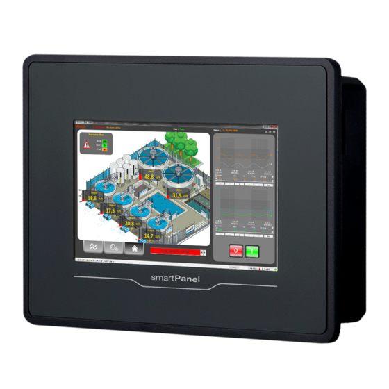
VIPA HMI Hardware description Properties 2.2 Properties General The VIPA smartPanel allows you to visualize and alter operating states and recent process values of a connected PLC. The smartPanel is a compact and modular Ò Ò embedded PC based on Windows EC 7. -
Page 9: Structure
VIPA HMI Hardware description Structure > Overview 2.3 Structure 2.3.1 Overview Front view Interfaces Display with touch sensitive area (Touch-Screen) Bottom view USB-A interface USB 2.0 RJ45 jack for Ethernet communication LAN RS232/RS422/RS485 interface COM Slot for DC 24V voltage supply HB160 | TP-smart | HA1-71A41-0 | en | 18-04... -
Page 10: Interfaces
VIPA HMI Hardware description Structure > Interfaces 2.3.2 Interfaces "Host"-USB-A Using the "Host"-USB-A interface USB mouse, keyboard, stick or USB hard discs can be connected. Ethernet connection The RJ45 jack provides the interface to the twisted pair cable, required for Ethernet. The Ethernet interface has got two LEDs for status display. -
Page 11: Memory Management
VIPA HMI Hardware description Structure > Memory management RS422/485 interface 9 pin SubD jack Logical states represented by voltage differences between the 4 cores Serial bus connection in 4-wire technology using full duplex mode Data communications up to a max. distance of 500m Data communication rate up to 115.2kBaud Serial bus connection in 2-wire technology using half duplex mode Power supply... -
Page 12: Dimensions
VIPA HMI Hardware description Dimensions USB storage media The connection of USB sticks and USB drives by use of the "Host"-USB-A interface is (USB 2.0) supported by the smartPanel. After connection the storage media is listed as USB Hard Disk under My Device. 2.4 Dimensions Installation dimensions Front panel (L x H) -
Page 13: General Data
VIPA HMI Hardware description General data 2.5 General data Conformity and approval Conformity 2014/30/EU EMC directive Approval Refer to Technical data others RoHS 2011/65/EU Restriction of the use of certain hazardous substances in electrical and electronic equipment Protection of persons and device protection Type of protection Rear: IP20;... -
Page 14: Technical Data
VIPA HMI Hardware description Technical data Standard Comment Emitted interference EN 61000-6-4 Class A (Industrial area) Noise immunity EN 61000-6-2 Industrial area zone B EN 61000-4-2 8kV at air discharge (degree of severity 3), 4kV at contact discharge (degree of severity 2) EN 61000-4-3 HF field immunity (casing) 80MHz …... - Page 15 VIPA HMI Hardware description Technical data Order no. HA1-71A41-0 CFast Slot Time Real-time clock buffered ü Clock buffered period (min.) Type of buffering Goldcap Load time for 50% buffering period Load time for 100% buffering period 10 h Accuracy (max. deviation per day) Operating controls Touchscreen resistive...
- Page 16 VIPA HMI Hardware description Technical data Order no. HA1-71A41-0 Inrush current 38 A I²t 0.33 A²s Power loss Status information, alarms, diagnostics Supply voltage display none Mechanical data Housing / Protection type Material PC + ABS Mounting mounting clips Protect type front side IP 66 Protect type back side IP 20...
-
Page 17: Deployment
VIPA HMI Deployment Installation Deployment 3.1 Installation Overview The smartPanel is suitable for the installation in operating tables and control cabinet fronts. The installation happens via the backside. The smartPanel is provided with a fixing technique that allows an easy connection with a crosstip screwdriver. A fast and easy device change is possible. -
Page 18: Commissioning
VIPA HMI Deployment Commissioning 3.2 Commissioning CAUTION! – Before commissioning the device must be brought to room tempera- ture. – At condensation the device must be absolutely dry before connected to power. – To avoid overheat during operation the device must not be laid open to direct sun light. -
Page 19: Firmware Update
VIPA HMI Deployment Commissioning > Firmware update 3.2.1 Firmware update Requirement To execute the firmware update an empty USB stick (at least 1GB) in FAT32 format is necessary. Current firmware on The latest firmware versions can be found in the service area at www.vipa.com. www.vipa.com CAUTION! When installing a new firmware you have to be extremely careful. - Page 20 VIPA HMI Deployment Commissioning > Firmware update Click on [Soft Reset (Recovery mode)]. ð The smartPanel reboots. The "System Settings" interface opens. Activate ‘Autorun scripts from external storage’ under ‘Services’ by moving the button to the right. Transfer firmware from Insert the prepared USB stick into the USB port of the smartPanel.
-
Page 21: Vipa Startup-Manager
VIPA HMI Deployment Commissioning > VIPA Startup-Manager 3.2.2 VIPA Startup-Manager Start screen As soon as the smartPanel is provided by power supply, the VIPA Startup-Manager will be loaded. At the first startup of the VIPA Startup-Manager the following start screen appears. - Page 22 VIPA HMI Deployment Commissioning > VIPA Startup-Manager With [...] under "Runtime path" res. "Project path" all existing runtimes res. projects on the smartPanel and the storage media are listed. Under "Delay Time" you can adjust a delay time > 0 by using the buttons [+] and [-]. 5 seconds are default.
- Page 23 VIPA HMI Deployment Commissioning > VIPA Startup-Manager Exit with [Finish]. Ò With "Copy" [...] you can copy Windows files on the smartPanel from a source path to a destination path. With "Autostart" you can select the automatic startup of the VNC server, the Movicon- TCP upload server resp.
-
Page 24: Connection To A Plc System
VIPA HMI Deployment Connection to a PLC system 3.3 Connection to a PLC system Overview For the inclusion into your PLC system several HMI/SCADA project-engineering plat- forms are at your disposal that has to be installed at an external PC. Here you may create your project, where appropriate simulate it and transfer it to the smartPanel via a connection that you’ve entered before. -
Page 25: Operating System Windows Embedded Compact 7
VIPA HMI Deployment Operating system Windows Embedded Compact 7 > General 3.4 Operating system Windows Embedded Compact 7 3.4.1 General Features File viewer for Word, Excel, PowerPoint and PDF ftp, Telnet, VNC and Web server RDP (Remote Desktop Protocol) Internet Explorer Registry Editor WordPad USB keyboard driver... -
Page 26: Structure
VIPA HMI Deployment Operating system Windows Embedded Compact 7 > Structure 3.4.2 Structure Icon Via icons on the desktop you gain direct access to the application related to the icon. Ò Desktop The desktop is the screen that is shown after login to Windows . - Page 27 VIPA HMI Deployment Operating system Windows Embedded Compact 7 > Structure Show desktop All windows are minimized and the desktop is shown. Software keyboard This button displays a keyboard at the screen. "Hide Input Panel" hides the key- board again. Software keyboard The button allows you to select one of the available software keyboards.
-
Page 28: Integrated Server
VIPA HMI Deployment Integrated server > General Set Display Via ‘Start è Settings è Control Panel è Display’ the dialog windows for the display properties opens. Here you can change the settings for the monitor options. Set Ethernet Parameters The dialog field for pre-setting an Ethernet address can be found in ‘Start è Settings è... -
Page 29: Ftp Server
VIPA HMI Deployment Integrated server > ftp server 3.5.2 ftp server By means of a ftp server data between client and server can be exchanged. Here you can copy, delete or create files and directories. Conditions for ftp access Depending on the ftp client your PC must have the following conditions for a ftp connec- tion. -
Page 30: Telnet Server
VIPA HMI Deployment Integrated server > Telnet server 3.5.3 Telnet server Telnet is a text based client-server protocol on TCP level. Using of a Telnet client like e.g. Ò the "MS-DOS console" in your Windows operating system you may execute text based all file remote functions at your smartPanel like copy, delete and create files and directo- ries. -
Page 31: Vnc Server
VIPA HMI Deployment Integrated server > VNC server 3.5.4 VNC server The smartPanel has an integrated VNC server (virtual network control) that allows the total control of the smartPanel with a PC via network. For this, a window displays the cur- rent smartPanel content for remote control. -
Page 32: Web Server
VIPA HMI Deployment Integrated server > Web server Click on [Options] and deactivate the field "Emulate 3 Buttons..." like shown at Mouse. Enter the IP address of the smartPanel at VNC server. Click on [OK] and enter the password vipatp. You can change the password over the configuration file, for this execute vncconfig.exe. -
Page 33: Access To The Network Resources
VIPA HMI Deployment Access to the network resources The login as web admin requires the following steps: Start the web browser at your PC and enter the following into the address bar: IP address/webadmin Enter the following into the authentification: User name: wince Password: vipatp 3.6 Access to the network resources... - Page 34 VIPA HMI Deployment Access to the network resources Configure network printer The configuration of a network printer happens with the following approach: Enter this command into the command prompt: \> net use printer name network printer Example: Printer name: Printer, network printer: \\testserver\printer Entry: \>...
-
Page 35: Installation Guidelines
VIPA HMI Installation Guidelines Basic rules for the EMC-equitable assembly of installations Installation Guidelines 4.1 Basic rules for the EMC-equitable assembly of installations General The installation guidelines contain information about the interference free deployment of a PLC system. There is the description of the ways, interference may occur in your PLC, how you can make sure the electromagnetic compatibility (EMC), and how you manage the isolation. - Page 36 VIPA HMI Installation Guidelines Basic rules for the EMC-equitable assembly of installations Coupling mechanism Cause Typical source Capacitate coupling Capacitate or electric coupling occurs Interference through parallel signal between conductors with different lines potential. The coupling is propor- Static discharge of the personnel tionate to the temporal change of the Contactors voltage.
- Page 37 VIPA HMI Installation Guidelines Basic rules for the EMC-equitable assembly of installations Proof the correct fixing of the lead isolation. – Data lines must be laid isolated. – Analog lines must be laid isolated. When transmitting signals with small ampli- tudes the one sided laying of the isolation may be favourable.
-
Page 38: Emc-Equitable Assembly
VIPA HMI Installation Guidelines EMC-equitable assembly 4.2 EMC-equitable assembly Mostly, measures for suppressing interference voltages are only taken, when the control is already in commission and the perfect receive of a wanted signal is disturbed. Causes for such interference's are in the most cases inadequate reference potentials, coming from mistakes at the device assembly and installation. -
Page 39: Emc-Equitable Cabling
VIPA HMI Installation Guidelines EMC-equitable cabling 4.3 EMC-equitable cabling Line routing Content of this section is the line routing of bus, signal and supply lines. Object of the line routing is to suppress the "slurring" at parallel lines. Line routing inside and For an EMC-equitable routing of the lines it is convenient to divide the cables in different outside of cubicles groups and install each group itself:... - Page 40 VIPA HMI Installation Guidelines EMC-equitable cabling Lightning protection CAUTION! Where cables and signal lines for PLC equipment are installed outside of buildings, the conditions for internal and external lightning protection must be satisfied. – Exterior lines should either be installed in metallic conduit pipes that is grounded on both ends or in steel-reinforced concrete cable trunks with continuously connected reinforcing.
- Page 41 VIPA HMI Installation Guidelines EMC-equitable cabling Avoid cables with foil-type screens as the foil can be easily damaged by tension and pressure at the point of attachment; this can result in reduced effectiveness of the screening action. As a rule you should always ground the screens of cables on both ends. This is the only way in which you can ensure that high frequency interference is attenuated prop- erly.
-
Page 42: Special Precautions Providing High Noise Immunity
VIPA HMI Installation Guidelines Special precautions providing high noise immunity 4.4 Special precautions providing high noise immunity Inductors require snubber Inductors controlled by your programmable controller (e.g. contactors and relays) do not networks normally require additional snubber networks or suppressors as the respective modules have been provided with the required components. -
Page 43: Checklist For The Emc-Compliant Installation Of Controllers
VIPA HMI Installation Guidelines Checklist for the EMC-compliant installation of controllers 4.5 Checklist for the EMC-compliant installation of controllers EMC-measures Space for Notes Connection of the inactive parts You should take special care to check the connections of: Module racks Frames Screen and protected earth conductor Are all the inactive metal parts interconnected by means of large-surface and low-...
Need help?
Do you have a question about the TP-smart HA1-71A41-0 and is the answer not in the manual?
Questions and answers