
Subscribe to Our Youtube Channel
Related Manuals for RKI Instruments T2A


Summary of Contents for RKI Instruments T2A
- Page 1 Operator’s Manual Part Number: 71-0529 Revision: P9 Released: 3/25/21 GlobalTestSupply www. .com Find Quality Products Online at: sales@GlobalTestSupply.com...
- Page 2 Typical calibration frequen- cies for most applications are between 1 and 3 months, but can be required more often or less often based on your usage. 2 • T2A Transmitter GlobalTestSupply www.
- Page 3 Product Warranty RKI Instruments, Inc. warrants gas alarm equipment sold by us to be free from defects in materials, workmanship, and performance for a period of one year from date of shipment from RKI Instruments, Inc. Any parts found defective within that period will be repaired or replaced, at our option, free of charge.
- Page 4 To avoid invalidating the certification, complete all wiring configurations BEFORE putting the T2A in the field. Once in the field, always use the RKI-distributed magnet to ensure non- intrusive calibration. Strong magnetic fields may interfere with the non-intrusive magnetic switches. A strong magnetic field may momentarily active a switch, or permanently disable the switch to the “on”...
-
Page 5: Table Of Contents
Mounting the T2A ........ - Page 6 Appendix A: 4-20 mA Signal ........... 44 6 • T2A Transmitter GlobalTestSupply www.
-
Page 7: Overview
Non-intrusive interface with the T2A is made possible by use of the magnetic tool included in the purchase of the device. The T2A display screen will always show the present concentration of gas being detected by the sensor assembly. -
Page 8: Specifications
Specifications Table 1 lists specifications for the T2A. Table 1: Specifications Target Gas Detection Range Increments Haz. Loc. Ammonia 0-100 ppm 1 ppm Cl. 1 Div. 2 0-200 ppm 0-400 ppm Carbon Monoxide 0-300 ppm Cl. 1 Div. 1 Chlorine 0-3.0 ppm... - Page 9 Weight 6 lbs. WARNING: When using the T2A, you must follow the instructions and warnings in this manual to assure proper and safe operation of the T2A and to minimize the risk of personal injury. Be sure to maintain and periodically calibrate the T2A as described in this manual.
-
Page 10: External Description
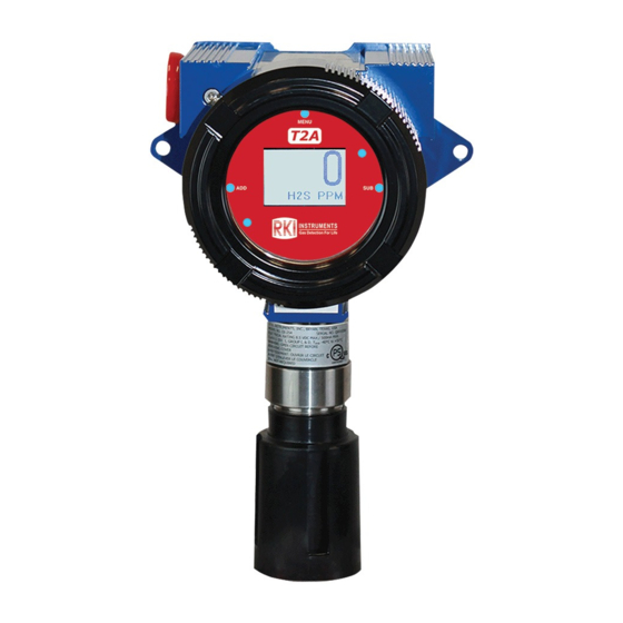
External Description Figure 1: T2A External Component Location MENU button Sensor housing assembly Front panel thumbscrew Rain guard Enclosure Magnetic tool Explosion proof plug ADD button SUB button Enclosure lid locking screw Mounting hole Display screen 10 • T2A Transmitter GlobalTestSupply www. -
Page 11: Internal Description
Internal Description Figure 2: Internal Component Location Faceplate assembly Faceplate mounting screws Power input/4-20 mA Microcontroller module output terminal block mounting screws Sensor housing socket Microcontroller module T2A Transmitter • 11 GlobalTestSupply www. .com Find Quality Products Online at: sales@GlobalTestSupply.com... -
Page 12: Exploded Drawing
(with flame arrestor for Class 1 Div. 1 assemblies; without flame arrestor for Class 1 Div. 2 assemblies) Sensor housing plug Rain guard Sensor housing base Enclosure ground screw Analog sensor board Dust plug 12 • T2A Transmitter GlobalTestSupply www. .com Find Quality Products Online at: sales@GlobalTestSupply.com... -
Page 13: Remote-Mounted Kit
Mounting the T2A 1. Consider the following when you select the mounting site. • Select a site where the T2A is not likely to be bumped or disturbed. Make sure there is sufficient room to perform start-up, maintenance, and calibration procedures. •... - Page 14 6.00 5.50 4.49 0.25 9.16 7.16 Ø 2.00 Figure 4: T2A Dimensions 14 • T2A Transmitter GlobalTestSupply www. .com Find Quality Products Online at: sales@GlobalTestSupply.com...
- Page 15 WARNING: If installed in a classified area, use appropriate construction technique to maintain the explosion proof classification of the assembly. 4.64 9.95 2.70 Figure 5: Remote-Mounted Kit’s Detector Junction Box Dimensions T2A Transmitter • 15 GlobalTestSupply www. .com Find Quality Products Online at: sales@GlobalTestSupply.com...
-
Page 16: Remote-Mounted Kit Wiring
7. Connect the ferruled wires to the color-coded terminals in the detector junction box. 8. Secure the detector junction box’s enclosure lid back onto the enclosure. 16 • T2A Transmitter GlobalTestSupply www. -
Page 17: Wiring Power And 4-20 Ma Output
Wiring Power and 4-20 mA Output The T2A requires +12 to +35 Volts of wired DC power to operate. It sends a 4-20 mA signal out through the power wires. CAUTION: The internal components can be static sensitive. Use caution when opening the enclosure and handling internal components. -
Page 18: Closing The Enclosure
4. Connect the power and 4-20 mA signal wires to the Input Terminal Block as shown below. CAUTION: If shielded cable is used, leave the cable shield’s drain wire disconnected and insulated at the T2A. You will connect the opposite end of the cable’s drain wire to the controller’s chassis (earth) ground. -
Page 19: Start Up
O-ring, potentially compromising the moisture seal, resulting in an unsafe environment. Start Up This section describes procedures to start up the T2A and place the T2A into normal operation. 1. Complete the installation procedures described earlier in this manual. - Page 20 2 hours 10 minutes Oxygen Ozone Phosphine Sulfur Dioxide 8. The T2A is factory-calibrated before shipping from RKI. If a full calibration is desired at startup, see page 35. 20 • T2A Transmitter GlobalTestSupply www. .com Find Quality Products Online at:...
-
Page 21: Operation
Normal Operating Mode While in Normal Operating Mode, the T2A continuously samples the air and updates the measured concentration of the target gas on the display screen. The display, when in Normal Operating Mode, appears as shown below. -
Page 22: Magnetic Buttons
SUB button Powering the Device When power is first applied to the T2A, the unit automatically powers on and begins the startup sequence. The directions below describe how to power off and power on the T2A once power has been applied. -
Page 23: Faults
The unit continuously registers that the system is in fault. When the fault is corrected, the unit will return to normal operating mode. For a list of the fault codes and warning symbols of the T2A, and their associated meaning, see page 32. -
Page 24: Product Settings And Configuration
The Product Settings and Configuration menu allows the end-user to tailor the device settings to meet their required specifications and/or site conditions. The T2A continues monitoring for gas while in the Product Settings and Configuration menu. The Product Settings and Configuration menu consist of the following screens: •... -
Page 25: System Information
2. Press and release the MENU button until the System Information screen appears. 3. Review the information displayed. 4. Use the MENU button to scroll through the rest of the Product Settings and Configuration menu and return to Normal Operating Mode. T2A Transmitter • 25 GlobalTestSupply www. .com Find Quality Products Online at: sales@GlobalTestSupply.com... -
Page 26: Zero/Calibration Timer Information
Auto Calibration: Sets the reading, after a predetermined amount of time, during calibration to the value entered during the auto calibration setup process. 1. If necessary, enter the Product Settings and Configuration menu by pressing and holding the MENU button for 6 seconds. 26 • T2A Transmitter GlobalTestSupply www. .com Find Quality Products Online at: sales@GlobalTestSupply.com... -
Page 27: 4-20 Ma Offset Settings
4-20 mA offset will need to be recalibrated. The factory default settings on the T2A for the 4-20 mA offset are 4.00 mA for the zero offset and 20.00 mA for the full-scale offset. -
Page 28: Display Screen Contrast Setting
The factory default setting on the T2A for the display screen contrast is 29, approximately 45% of the contrast scale. The contrast setting ranges from 1 to 64. -
Page 29: Return To Factory Default Settings
Normal Operating Mode. Return to Factory Default Settings Returning the T2A to its factory default settings will reset all customization of the device, including the zero and calibration settings of the sensor element. A factory default does not change the gas type. -
Page 30: Reset Zero & Calibration Values
6. Use the MENU button to scroll through the rest of the Product Settings and Configuration menu and return to Normal Operating Mode. NOTE: If the T2A is reset to the factory default settings, ALL configuration steps MUST be repeated and the device MUST then be zeroed and calibrated for proper operation of the device. -
Page 31: Maintenance
6. Press and release the MENU button to return to Normal Operating Mode. NOTE: If the T2A’s stored Zero and Calibration values are reset, the device MUST be zeroed and calibrated for proper and safe operation of the device. -
Page 32: Troubleshooting
3. Replace the sensor interface board. • a sensor interface board error. If the T2A does not turn on, confirm the presence of 12-35 VDC at the Input Terminal Block using a DMM set to read in DC volts. Desiccant Replacement Each T2A comes with a desiccant bag installed in the junction box. -
Page 33: Sensor Replacement
DO NOT use any metal objects or tools to remove the sensing element from the sensor adapter board. 1. Turn off power to the T2A. 2. Unscrew the rain guard. 3. Unscrew and remove the sensor housing cap from the sensor housing base. Set aside. - Page 34 6. Screw the sensor housing cap back onto the sensor housing base, ensuring that the sensor housing cap is only tightened hand tight. 7. Press the ADD button to turn the T2A on. 8. Allow the detector to warmup for the appropriate amount of time as shown below, depending on the sensor type.
-
Page 35: Calibration
Auto Cal, RKI recommends a concentration between 10 and 18% O . For all other sensors, RKI recommends using 50% of the full scale value of your detected gas.) T2A Transmitter • 35 GlobalTestSupply www. .com Find Quality Products Online at:... -
Page 36: Zeroing The Sensor
4. If the sensor is not in clear air: a. Unscrew and remove the rain guard from the assembly. b. Install the calibration cup to the T2A’s sensor housing. c. Screw the regulator into the zero air calibration cylinder. d. Use the sample tubing to connect the regulator to the calibration cup. -
Page 37: Calibrating The Sensor (Manual Cal)
If you are accessing Manual Cal from Normal Operating Mode, press MENU twice. 3. Unscrew and remove the rain guard from the assembly. 4. Install the calibration cup to the T2A’s sensor housing. T2A Transmitter • 37 GlobalTestSupply www. - Page 38 Zero/Calibration Timer Information screen. 11. When calibration is complete, remove the calibration cup from the sensor housing and reinstall the rain guard. 12. Use the MENU button to return to Normal Operating Mode. 38 • T2A Transmitter GlobalTestSupply www. .com Find Quality Products Online at: sales@GlobalTestSupply.com...
-
Page 39: Calibrating The Sensor (Auto Cal)
5. Use the ADD and SUB buttons to adjust the concentration match the concentration shown on the calibration cylinder. For detectors using a surrogate gas, adjust the reading to match the surrogate gas concentration multiplied by the factor listed in Table 2 on page 36. T2A Transmitter • 39 GlobalTestSupply www. .com Find Quality Products Online at: sales@GlobalTestSupply.com... - Page 40 7. Unscrew and remove the rain guard from the assembly. 8. Install the calibration cup to the T2A’s sensor housing. 9. Screw the regulator into the calibration cylinder. 10. Use the sample tubing to connect the regulator to the calibration cup.
- Page 41 15. Use the MENU button to Normal Operating Mode. T2A Transmitter • 41 GlobalTestSupply www. .com Find Quality Products Online at: sales@GlobalTestSupply.com...
-
Page 42: Parts List
Parts List Table 3 lists replacement parts and accessories for the T2A. Table 3: Parts List Part Number Description 47-5110-XX Cable with connector for remote-mounted kit (specify length in 1-foot increments, up to 250 feet, when ordering) 61-2001 Detection junction box for remote-mounted kit, explosion-proof... - Page 43 Regulator with gauge and knob, 0.5 LPM, for 34 liter aluminum, 58 liter, and 103 liter calibration cylinders (cylinders with internal threads) 81-1183 Calibration cup with 3 foot tube 81-1184 Rain guard 82-0101RK Magnetic wand T2A Transmitter • 43 GlobalTestSupply www. .com Find Quality Products Online at: sales@GlobalTestSupply.com...
-
Page 44: Appendix A: 4-20 Ma Signal
4 mA representing the lowest end of the range and 20 mA the highest. The relationship between the current loop and the gas value is linear. In addition, the T2A uses values below 4 mA to indicate special status conditions, as shown below: 4-20 mA Ranges... - Page 45 (DMM), or current meter, may be used in conjunction with the controller and/or to test the 4-20 mA current loop signal. To measure the current, place the meter probes in line with the current loop. T2A Transmitter • 45 GlobalTestSupply www.
Need help?
Do you have a question about the T2A and is the answer not in the manual?
Questions and answers