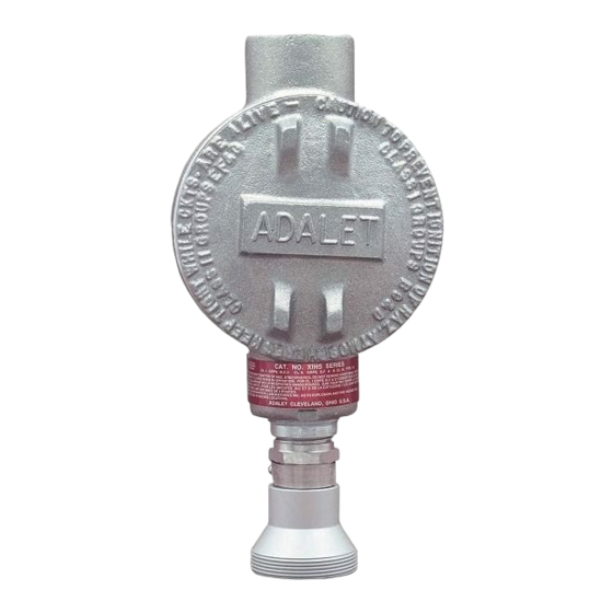
Summary of Contents for RKI Instruments 65-2462RK
- Page 1 65-2462RK Hydrogen Transmitter Operator’s Manual Part Number: 71-0554 Revision: P1 Released: 4/15/21 RKI Instruments, Inc. www.rkiinstruments.com...
- Page 2 Typical calibration frequen- cies for most applications are between 3 and 6 months, but can be required more often or less often based on your usage. 2 • 65-2462RK Hydrogen Transmitter...
- Page 3 Product Warranty RKI Instruments, Inc. warrants gas alarm equipment sold by us to be free from defects in materials, workmanship, and performance for a period of one year from date of shipment from RKI Instruments, Inc. Any parts found defective within that period will be repaired or replaced, at our option, free of charge.
-
Page 4: Table Of Contents
Parts List ..............19 4 • 65-2462RK Hydrogen Transmitter... -
Page 5: Overview
Overview This manual describes the 65-2462RK hydrogen transmitter. This manual also describes how to install, start up, configure, maintain, and calibrate the transmitter when it is used with a gas monitoring controller. A parts list at the end of this manual lists replacement parts and accessories for the hydrogen transmitter. -
Page 6: Description
A rainshield screws onto the bottom of the detector (flame arrestor end). The rainshield helps protect the detector from rain and debris in the monitoring environment. Four color-coded leads extend from the top of the detector. The leads allow you to connect the detector to the amplifier. 6 • 65-2462RK Hydrogen Transmitter... -
Page 7: Amplifier
The span pot is located to the right of the zero pot (see Figure 2). Use a small flat blade screwdriver to turn the span pot’s adjustment screw and adjust the amplifier’s gas response output during the calibration procedure. 65-2462RK Hydrogen Transmitter • 7... -
Page 8: Junction Box
• Select a site where the target gas is likely to be found first. For lighter gases, mount the detec- tor near the ceiling; for heavier gases, mount the detector near the floor. 8 • 65-2462RK Hydrogen Transmitter... - Page 9 J Box 3/4 x 1/2 Reducing Bushing Hydrogen Detector Figure 3: Mounting the Hydrogen Transmitter 2. At the monitoring site you select, hang or mount the junction box with the detector facing down (see Figure 3). 65-2462RK Hydrogen Transmitter • 9...
-
Page 10: Wiring The Hydrogen Transmitter
CAUTION: Do not route power and transmitter wiring through the same controller conduit hub. The power cable may disrupt the transmission of the transmitter signal to the controller. 11. Connect the wires to the applicable detector/transmitter terminal strip at the controller as shown in Figure 4. 10 • 65-2462RK Hydrogen Transmitter... - Page 11 12. If shielded cable is used, connect the cable’s drain wire to an available chassis (earth) ground at the controller. RKI controllers typically have a ground stud that can be used to ground the cable’s drain wire. 65-2462RK Hydrogen Transmitter • 11...
-
Page 12: Startup
- test point. 7. Turn the regulator knob counterclockwise to open the regulator. 8. Allow the calibration gas to flow for one minute. 9. Verify a voltmeter reading of 100 mV (±2 mV). 12 • 65-2462RK Hydrogen Transmitter... -
Page 13: Maintenance
3. If the fail condition continues, • The transmitter’s replace the detector. zero reading is low 4. If the fail condition continues, enough to cause a contact RKI for further fail condition. instruction. • The transmitter is malfunctioning. 65-2462RK Hydrogen Transmitter • 13... -
Page 14: Replacing Components Of The Hydrogen Transmitter
8. Connect the detector leads to the detector terminal strip as shown in Table 3 below and Figure 4 on page 11 of this manual. Table 3:Reconnecting the Hydrogen Detector to the Amplifier Detector Lead Detector Terminal Strip LEL “R” White LEL “W” Green LEL “G” Black LEL “B” 14 • 65-2462RK Hydrogen Transmitter... - Page 15 PWR/SIG “S” S (4 - 20 mA In) PWR/SIG “+” + 24V Table 5:Reconnecting the LEL Detector to the Amplifier Amplifier Detector Detector Lead Terminal Strip DETECTOR “R” DETECTOR “W” DETECTOR “G” GREEN DETECTOR “B” 65-2462RK Hydrogen Transmitter • 15...
-
Page 16: Calibration Frequency
Although there is no particular calibration frequency that is correct for all applications, a calibration frequency of every 9 to 12 months is adequate for most hydrogen transmitter applications. Unless experience in a particular application dictates otherwise, RKI Instruments, Inc. recommends a calibration frequency of every 9 months. -
Page 17: Zeroing With Nitrogen
6. Turn the regulator knob clockwise to close the regulator. 7. Unscrew the regulator from the calibration cylinder. Leave the sample tubing connected to the regulator and the calibration cup. 65-2462RK Hydrogen Transmitter • 17... -
Page 18: Zeroing With Background Gas
4. When the controller display reading falls below the alarm setpoints, return the controller to normal operation. 5. Verify that the controller display reading decreases and stabilizes at 0% volume. 6. Store the components of the calibration kit in a safe and convenient place. 18 • 65-2462RK Hydrogen Transmitter... -
Page 19: Parts List
Amplifier with gasket (specify target gas and that the 61-0140RK detector is being used when ordering) 65-2462RK Hydrogen transmitter (includes detector and amplifier; specify target gas when ordering) 71-0554 65-2462RK Hydrogen Transmitter Operator’s Manual (this document) 81-0022RK-01 Calibration cylinders, 4% volume H in N , 34 liter steel 81-0076RK-01...


Need help?
Do you have a question about the 65-2462RK and is the answer not in the manual?
Questions and answers