RKI Instruments M2A-XL Operator's Manual
Hide thumbs
Also See for M2A-XL:
- Operator's manual (67 pages) ,
- Operator's manual (61 pages) ,
- Operator's manual (64 pages)

Related Manuals for RKI Instruments M2A-XL


Summary of Contents for RKI Instruments M2A-XL
- Page 1 M2A-XL Transmitter Operator’s Manual Part Number: 71-0610 Revision: P1 Released: 10/20/22 RKI Instruments, Inc. www.rkiinstruments.com...
- Page 2 Frequency of calibration depends upon the type of use you have and the sensor types. For most applications, typical calibration frequencies are between 3 and 6 months but can be more often or less often based on your usage. 2 • M2A-XL Transmitter Operator’s Manual...
- Page 3 Product Warranty RKI Instruments, Inc. warrants gas alarm equipment sold by us to be free from defects in materials, workmanship, and performance for a period of one year from date of shipment from RKI Instruments, Inc. Any parts found defective within that period will be repaired or replaced, at our option, free of charge.
-
Page 4: Table Of Contents
Viewing & Changing M2A-XL Parameters ........ - Page 5 Using the M2A-XL in a 4-wire Modbus System ....... 77...
-
Page 6: Chapter 1: Introduction
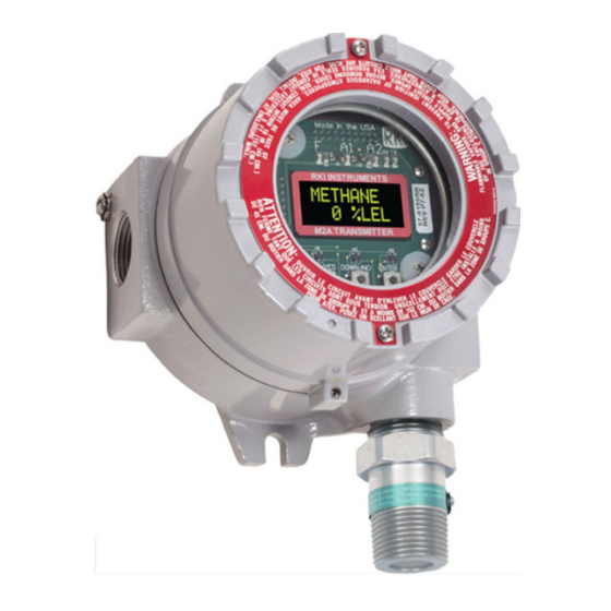
The M2A-XL displays the current gas reading on an OLED display which is visible through the window in the cover (front face) and provides a 4 - 20 mA signal which indicates the target gas reading for use by a gas monitoring controller, recording device, or programmable controller. -
Page 7: Specifications
Specifications Table 1 lists specifications for the M2A-XL. Table 1: M2A-XL Specifications Combustible Gas/Carbon Dioxide (CO • Catalytic LEL: 0 - 100% LEL, 1% LEL increments (CH calibration unless otherwise specified. H specific detector available) • Catalytic CH ppm: 0 - 9000 ppm, 20 ppm increments •... - Page 8 Table 1: M2A-XL Specifications Ammonia (0 - 75.0 ppm and 0 - 100 ppm): 12 ppm / 25 ppm Ammonia (0 - 200 ppm): 25 ppm / 35 ppm Ammonia (0 - 500 ppm): 35 ppm / 300 ppm Arsine: 0.20 ppm / 0.50ppm...
- Page 9 Toxic Sensors (ESM-01 Type and CT-7 Series Type): ± 10% of reading or ± 5% of full scale (whichever is greater) These are RKI factory settings. See “Viewing & Changing M2A-XL Parameters” on page 47 to change the alarm settings.
-
Page 10: Chapter 2: Description
The M2A-XL’s cast aluminum junction box is dust and weather resistant. The junction box also protects the M2A-XL and all connections made to it. Use the three 3/4 NPT conduit ports to mount the detector to the junction box (factory installed in the bottom port) and connect wiring from an external device (left port). - Page 11 Use the junction box’s two mounting holes to mount the M2A-XL to a vertical surface at the monitoring site. The window in the cover on the front of the junction box allows you to view the OLED display and use the magnetic wand to actuate the magnetic control switches so you can perform non-intrusive calibration.
- Page 12 The table below outlines the M2A-XL part numbers and replacement detector part numbers for the infrared (IR) detectors. Table 3: Infrared (IR) Detectors...
- Page 13 (65-2514RK) and the non-explosion proof capillary type detector (65-2494RK) has a replaceable plug-in sensor inside the detector housing. The entire oxygen detector must be removed if replacement is required for the 65-2510RK. M2A-XL Transmitter Operator’s Manual Chapter 2: Description • 13...
- Page 14 The table below outlines the M2A-XL part numbers and replacement detector part numbers for the oxygen detectors. Table 4: Oxygen Detectors M2A-XL Part Target Gas, Range Detector Used Number Oxygen, 0 - 25% 65-2643RK-05 65-2514RK (capillary, CSA) 65-2644RK 65-2510RK (partial pressure)
- Page 15 The table below outlines the M2A-XL part numbers and replacement detector part numbers for the CO and H S detectors. Table 5: CO and H S Detectors M2A-XL Part Target Gas, Range Detector Used Number CO, 0 - 300 ppm...
- Page 16 ESM-01 detector, remove the splashguard to allow access to the sensor that protrudes through the detector housing cap. You can then push the appropriate ESM-01 calibration cup onto the sensor. The table below outlines the M2A-XL part numbers and replacement detector part numbers for the ESM-01 detectors. Table 6: ESM-01 Detectors...
- Page 17 An adhesive backed gasket inside the detector housing cap helps ensure that the sensor remains plugged into the detector housing body. The table below outlines the M2A-XL part numbers and replacement detector part numbers for the CT-7 Series detectors.
- Page 18 65-2670-NH3-5 65-2302-NH3-5 , 0 - 10 ppm 65-2670-SO2-10 65-2302-SO2-10 Detector Housing Body (different for each detector type) Cap Gasket Plug-in Sensor Hydrophobic Membrane Detector Housing Cap Figure 8: CT-7 Series Detectors 18 • Chapter 2: Description M2A-XL Transmitter Operator’s Manual...
-
Page 19: Internal Description
RS-485 Modbus output signal. The 4 - 20 mA signal may be used by a recording device, gas monitor controller, or programmable controller. The Modbus output may be used to connect the M2A-XL to a Modbus network. The terminal PCB also controls three relays: one fail and two gas alarm. - Page 20 The power/signal terminal strip is a three position plug-in style terminal strip located at the top of the left terminal column. It is used to connect 24 VDC power to the M2A-XL and to connect the 4 - 20 mA output signal to a device.
- Page 21 M2A-XL, all four terminals are used to connect the detector to the M2A-XL. For a toxic or oxygen M2A-XL, only two of the terminals are used for connecting a detector; two terminals are dedicated for connecting a toxic detector and two are dedicated for connecting an oxygen detector (only one detector can be installed).
- Page 22 Figure 12: Control PCB Component Location OLED Display The OLED display is located at the top of the control PCB. It indicates the current gas reading and displays messages and parameters in the M2A-XL’s programs. 22 • Chapter 2: Description M2A-XL Transmitter Operator’s Manual...
- Page 23 The M2A-XL includes five status LEDs that are located above the display (see Figure 12). • Fail LED The fail LED turns on when the M2A-XL is experiencing a fail condition. A fail condition can be caused by a detector failure or low detector signal.
- Page 24 • Alarm 1 LED The alarm 1 LED is on when the M2A-XL is experiencing an alarm 1 condition. • Alarm 2 LED The alarm 2 LED is on when the M2A-XL is experiencing an alarm 2 condition. • RX & TX LED’s These LED’s indicate data being received (RX) and transmitted (TX) when the M2A-XL’s...
-
Page 25: Chapter 3: Installation & Startup
1. Select a mounting site that is representative of the monitoring environment. Consider the following when you select the mounting site. • Select a site where the M2A-XL is not likely to be bumped or disturbed. Make sure there is sufficient room to perform start-up, maintenance, and calibration procedures. - Page 26 3/4 NPT 4.86 5.66 Conduit Port, Plugged 2.82 3/4 NPT Conduit Port 7.5 max 1.9 max Ø 0.25, 2X 1.00 Figure 15: Outline & Mounting Dimensions, IR Combustible & CO 26 • Chapter 3: Installation & Startup M2A-XL Transmitter Operator’s Manual...
- Page 27 7.0 max 1 1/2-20 For 1.5 max Calibration Cup Ø 0.25, 2X 1.00 Figure 17: Outline & Mounting Dimensions, Replaceable Sensor, H S, CO, and Oxygen, Non Explosion Proof M2A-XL Transmitter Operator’s Manual Chapter 3: Installation & Startup • 27...
- Page 28 Conduit Port, Plugged 2.82 3/4 NPT Conduit Port 8.7 max 3.4 max Ø 0.25, 2X 1.00 Figure 18: Outline & Mounting Dimensions, H S, CO, and Oxygen, CSA, Explosion-Proof 28 • Chapter 3: Installation & Startup M2A-XL Transmitter Operator’s Manual...
- Page 29 3/4 NPT 4.86 5.66 Conduit Port, Plugged 2.82 3/4 NPT Conduit Port 10.5 max Ø 0.25, 2X 4.82 max 1.00 Figure 19: Outline & Mounting Dimensions, ESM-01 Toxic M2A-XL Transmitter Operator’s Manual Chapter 3: Installation & Startup • 29...
-
Page 30: Wiring The M2A-Xl Transmitter
1.40 max Ø 0.25, 2X 1.00 Figure 20: Outline & Mounting Dimensions, CT-7 Series Wiring the M2A-XL Transmitter WARNING: Always verify that the power source is OFF before making any wiring connections. 1. Remove the junction box cover. 2. Grasp the control PCB by its edges. - Page 31 LEL W, green wire to terminal labeled LEL G, black wire to terminal labeled LEL B. Black Green White Figure 21: Catalytic LEL and ppm Detector Wiring Black Green White Figure 22: IR Combustible/IR CO Detector Wiring M2A-XL Transmitter Operator’s Manual Chapter 3: Installation & Startup • 31...
- Page 32 White Figure 23: Partial Pressure Oxygen Detector Wiring Green White Figure 24: CSA Capillary Type Oxygen Detector Wiring Green White Figure 25: Capillary Type Replaceable Sensor Oxygen Detector Wiring 32 • Chapter 3: Installation & Startup M2A-XL Transmitter Operator’s Manual...
- Page 33 Non Explosion Proof CO or H S Gas Detectors Red wire to terminal labeled TOXIC +, black wire to terminal labeled TOXIC -. Black Figure 27: H S/CO Detector Wiring M2A-XL Transmitter Operator’s Manual Chapter 3: Installation & Startup • 33...
- Page 34 (see chart below) to the terminal labeled TOXIC + and the black wire to the terminal labeled TOXIC -. Black See Chart Wire Color Gas Type Brown AsH3 Yellow White Green Blue Figure 28: ESM-01 Toxic Detector Wiring 34 • Chapter 3: Installation & Startup M2A-XL Transmitter Operator’s Manual...
- Page 35 1 relay terminal strip may be removed by grasping them with your fingers if the adjacent terminal strips have been removed. WARNING: If the M2A-XL is installed in a hazardous location, use appropriately rated conduit, conduit fittings, and appropriate construction technique that complies with the local electrical code.
- Page 36 The number of cables or wires needed will depend on whether the M2A-XL is wired to a gas monitoring controller or just to power, whether any relays are used, and whether the Modbus output is used.
- Page 37 The S terminal has a 4 - 20 mA output, but if you do not need to monitor this signal and do not connect to the S terminal to access this signal, the M2A-XL will still function completely.
-
Page 38: Start Up
4. If necessary, turn on the controller or other monitoring device that is connected to the M2A- 5. The OLED display will indicate the firmware version when the M2A-XL is first powered up and will then count down a one minute warm-up period before normal operation begins. - Page 39 58 or “Calibration, Oxygen Version” on page 63. Verify that the M2A-XL is in a fresh air environment (environment known to be free of the target gas and combustible or toxic gas vapors and of normal oxygen content, 20.9%).
- Page 40 3. Press and release the UP/YES button. ENTER will alternate with FreshAir on the top display line and the current oxygen reading will be on the bottom display line. 4. Press and release the ENTER button. The M2A-XL will perform a span operation and then the display will indicate ZERO w/Cal Gas?.
-
Page 41: Chapter 4: Operation
2. Continue holding the DOWN/NO button to keep the Information Screen on the display. The top line indicates the operating voltage that is connected to the M2A-XL. The second line indicates the firmware that is running, version 6.0 in this example, and the M2A-XL’s hardware version, version 2A in this example. -
Page 42: 4 - 20 Ma Signal Output Operation
There are several circumstances where the signal output will not track the display reading but will behave as follows: • When the M2A-XL is in its warm-up period, the signal output will be fixed at 1.2 mA. • When the M2A-XL’s gas type is changed, the M2A-XL will enter Configuration Mode for you to verify the parameter settings. -
Page 43: Alarm Indications
• LowPower message and actual voltage of incoming DC power If the M2A-XL is in both an alarm 1 and an alarm 2 condition, both alarm LEDs are on and the display alternates between the gas reading and the ALMS 1&2 message. - Page 44 • The alarm 2 relay energizes. NOTE: If the M2A-XL is in both an alarm 1 and alarm 2 condition, both the A1 and A2 LEDs will be on, the gas reading will alternate with the ALMS 1&2 message, and both alarm relays will energize.
- Page 45 Responding to a Fail Condition 1. Verify that the detector wiring is correctly and securely connected. 2. If the M2A-XL has a replaceable plug-in sensor, verify that the replaceable plug-in sensor in the detector housing is properly installed. M2A-XL Transmitter Operator’s Manual...
- Page 46 Low Power Alarm Low Power Alarm Indications The M2A-XL senses a low power condition when the DC power source is 9.5 volts or less. WARNING: While in a low power condition, the M2A-XL is not an active gas monitor. When the M2A-XL senses a low power condition, it alerts you as follows: •...
-
Page 47: Chapter 5: Configuration Mode
If the currently displayed parameter is OK, press the ENTER button to proceed to the next parameter. Table 11 lists the M2A-XL parameters you can set. Table 11 also lists the factory set value for each parameter. M2A-XL Transmitter Operator’s Manual... - Page 48 Table 11: Configuration Parameters Parameter Description (Factory Set Value) ALARM-1 (level) The gas reading at which the M2A-XL initiates an alarm 1 condi- tion. (See Table 1 on page 7) ALARM-1 (activation) Indicates if the alarm 1 circuit is activated by gas readings...
- Page 49 Parameter Description (Factory Set Value) The amount of time the M2A-XL delays activation of the alarm 2 A2 OnDy (alarm 2 on delay) circuit once an alarm 2 condition is initiated. It can be set in 1 sec- (1 secs) ond increments from 0 - 60 seconds, in 1 minute increments from 1 - 15 minutes, and in 15 minute increments from 15 - 60 minutes.
- Page 50 Go back to step 3 and continue. If you wish to save the adjustments made, press and release the UP/YES button. Config Saved is indicated on the display for a few seconds and the M2A-XL returns to normal operation.
-
Page 51: Chapter 6: Gas Type Mode
Chapter 6: Gas Type Mode Overview This chapter describes how to use Gas Type Mode to select the M2A-XL’s gas type. The gas type determines the target gas and detection range. The combustible gas/CO and toxic/oxygen M2As have a different terminal PCB and run on different firmware. Your M2A-XL will only have gas type choices available that it can support. - Page 52 0 - 50.0 ppm CLO2 0 - 1.00 ppm CLO2 0 - 3.00 ppm 0 - 500 ppm 0 - 200 ppm 0 - 15.0 ppm CLO2 0 - 5.00 ppm 52 • Chapter 6: Gas Type Mode M2A-XL Transmitter Operator’s Manual...
- Page 53 5. To discard the gas type change, press and release the DOWN/NO button. The display will ask DO OVER? YES/NO. Press the DOWN/NO button. The display will ask ABORT? YES/ NO. Press the UP/YES button. The M2A-XL will return to normal operation without changing the gas type.
- Page 54 11. See “Calibration, Combustible Gas, CO2, and Toxic Versions” on page 58 or “Calibration, Oxygen Version” on page 63 for calibration instructions. NOTE: When calibrating an M2A-XL after changing the gas type, the M2A-XL will not ask if you want to calibrate, or whether you want to perform a fresh air adjustment, span adjustment or zero adjustment.
-
Page 55: Chapter 7: Maintenance
This section describes a recommended preventive maintenance schedule to ensure the optimum performance of the M2A-XL. It includes daily, quarterly, and biannual procedures. Daily Verify a display reading of zero (20.9% for an oxygen M2A-XL). Investigate significant changes in the reading. Quarterly Calibrate M2As that do not have an IR detector as described in “Calibration, Combustible Gas,... -
Page 56: Troubleshooting
The troubleshooting guide describes symptoms, probable causes, and recommended action for problems you may encounter with the M2A-XL. NOTE: This troubleshooting guide describes M2A-XL problems only. If the M2A-XL is connected to a controller, see the controller operator’s manual for problems you may encounter with the controller. - Page 57 Table 14: Troubleshooting the M2A-XL Condition Symptom(s) Probable Causes Recommended Action Fail • M2A-XL indicates • The detector wiring to 1. Verify that the detector wiring is correct Condition a fail condition. the terminal PCB is and secure. disconnected or •...
-
Page 58: Calibration Frequency
3 months for a non-IR M2A-XL or every 6 months for an IR M2A-XL may be necessary. For combustible gas detection with an M2A-XL that uses a catalytic detector, if potential catalyst poisons are known or likely to be present, more frequent calibration than every 3 months will be necessary. - Page 59 The calibration gas can then be removed and the M2A-XL will continue to display this reading and retain it in its memory until the span adjustment procedure is completed.
- Page 60 NOTE: While in the calibration program, if there is no switch activity for the calibration time- out period the unit will return to normal operation. See “Viewing & Changing M2A-XL Parameters” on page 47 for instructions to set the calibration time-out.
- Page 61 The M2A-XL will continue to display the minimum gas response on the display and retain the response level in its memory. 9. Press and release the ENTER button. The M2A-XL will perform a fresh air adjustment and the display will indicate SPAN w/Cal Gas?.
- Page 62 CO concentration between 30 and 300 ppm). 8. The M2A-XL will perform a span operation. The display will indicate SPAN Gas PASS for a few seconds, then indicate SPAN Gas SAVED before indicating Leaving CAL Mode for a few seconds.
-
Page 63: Calibration, Oxygen Version
10. Store the components of the calibration kit in a safe place. Calibration, Oxygen Version This section describes how to calibrate the oxygen version of the M2A-XL. It includes procedures to prepare for calibration, enter Calibration Mode, set the fresh air (span) reading, set the zero reading, and return to normal operation. - Page 64 The calibration gas can then be removed and the M2A-XL will continue to display this reading and retain it in its memory until the zero adjustment procedure is completed.
- Page 65 The M2A-XL will continue to display the maximum gas response on the display and retain the response level in its memory. 9. Press and release the ENTER button. The M2A-XL will perform a fresh air adjustment and the display will indicate ZERO w/Cal Gas?.
-
Page 66: Replacing Components Of The M2A-Xl
8. Press and release the ENTER button. The M2A-XL will perform a zero operation. The display will indicate ZERO Gas PASS for a few seconds, then indicate ZERO Gas SAVED before indicating Leaving CAL Mode for a few seconds. NOTE: If the zero adjustment fails, see “Troubleshooting” on page 56 for recommended actions. - Page 67 If necessary for environmental conditions, apply thread sealant or Teflon tape to the hub and/or detector threads to seal them. M2A-XL Transmitter Operator’s Manual Chapter 7: Maintenance • 67...
- Page 68 PCB so it will not be damaged by the cover when it is screwed back 13. Secure the junction box cover to the junction box. 14. Turn on or reconnect power to the M2A-XL. NOTE: For all gases except ClO , allow the replacement detector to warm up for 15 minutes before you continue with the next step.
- Page 69 4. If you are replacing a CO sensor, remove the rubber boot and charcoal filter from the old sensor. NOTE: RKI instruments recommends replacing the charcoal disk filter whenever a CO sensor is replaced. If you are replacing the 65-2428 explosion-proof H S detector’s sensor, remove the rubber...
- Page 70 H S and certain hydrocarbons. If you are experiencing unexplained upscale readings on a CO M2A-XL, the charcoal filter may be saturated and no longer scrubbing out interfering gases and it may be necessary to change the charcoal filter.
- Page 71 Replacing an ESM-01 Plug-in Sensor 1. Turn off or disconnect power to the M2A-XL. 2. Unscrew the detector cap from the detector housing body. Take care not to lose the cap gasket. If the splashguard begins to unscrew from the detector cap, make sure to remove the detector cap also.
- Page 72 Replacing the Hydrophobic Membrane (CT-7 Series Toxic Detector) 1. Turn off or disconnect power to the M2A-XL. 2. Unscrew the detector housing cap from the detector housing body. 3. Unplug the plug-in sensor from the four-socket pattern in the detector housing body.
-
Page 73: Chapter 8: Rs-485 Modbus Output
This chapter describes the M2A-XL’s RS-485 Modbus output and how to configure the M2A-XL to make use of it. It also discusses how to wire the M2A-XL into a Modbus system. The M2A-XL provides an RS-485 serial communications interface. It is a Modbus Slave Device, supporting 2-wire RS-485 Modbus RTU serial communications. - Page 74 Modbus system. Every M2A-XL is supplied with a ground jumper (a jumper block) installed onto this header. If the M2A-XL isn’t wired into a Modbus system or if it is wired into one as shown in Figure 33, the ground jumper should be installed. If the M2A-XL is wired in a Modbus system as shown in Figure 32, the ground jumper should be removed.
- Page 75 Alternate Modbus Wiring For Existing Installations Although the wiring shown in Figure 32 is recommended, it is possible to wire the M2A-XL into a Modbus system with only 4 wires in situations where a pre-existing system is being replaced and wiring is already in place. This should only be done if wiring for a system that is being replaced is already installed and it is not practical to run another wire.
- Page 76 When the M2A-XL is installed in a Modbus system, this jumper must be installed in an M2A-XL that is at the end of a Modbus line. Any M2A-XL in a Modbus system that is not at the end of a line must have the termination jumper removed (see Figure 34 & Figure 35 below).
-
Page 77: Using The M2A-Xl In A 4-Wire Modbus System
Using the M2A-XL in a 4-wire Modbus System Although the M2A-XL is a 2-wire Modbus RTU device, it can be used with a 4-wire Modbus controller if the system wiring is modified as follows: • Connect the controller’s TxD0 and RxD0 wires together and use this connection as the 2- wire Modbus D0 signal. - Page 78 If you wish to change some of the adjustments made, press and release the DOWN/NO button. The DO OVER? YES/NO message will display. Press and release the UP/YES button. The Re-do MB Setup message will display and the M2A-XL will return to the first adjustable parameter. Go back to step 3 and continue.
-
Page 79: Supported Modbus Functions
Supported Modbus Functions The M2A-XL supports Function Code 03: Read Holding Registers and Function Code 16: Write Registers. Function Code 03: Read Holding Registers There are a total of 40 registers available to be read via this Function Code. Registers 1 - 2 The format (bit &... - Page 80 0 = Not Energized 1 = Energized Alarm 2 Relay Status 0 = Not Energized 1 = Energized Alarm 1 Relay Status 0 = Not Energized 1 = Energized 80 • Chapter 8: RS-485 Modbus Output M2A-XL Transmitter Operator’s Manual...
- Page 81 Register 3 is the supply voltage (0.1 volt per count). Registers 4 - 11 The 16 bytes in these registers contain the same ASCII text information that is displayed on the M2A-XL’s OLED (not NULL Terminated). Register 12 Register 12 is the range (full scale readout).
- Page 82 Register 36 Register 36 is calibration month (upper byte) and day (lower byte). This is zero based (e.g. January=0 and the 1st=0). Register 37 Register 37 is the calibration year. 82 • Chapter 8: RS-485 Modbus Output M2A-XL Transmitter Operator’s Manual...
- Page 83 Function Code 16: Write Registers There are 21 registers in Function Code 16 that can be used to write to the M2A-XL. This section only describes Register 16 because it can be used to reset an alarm condition. For a complete description of Function Code 16, see “Appendix C: Function Code 16 Registers”...
- Page 84 Register 16 Register 16 performs the same function as the ENTER button on the M2A-XL. It is useful for remotely silencing alarms. With the M2A-XL in an alarm condition, bit [0] can be used to silence NOTE: Register 40 in Function Code 03, the remote configuration register, must be set to 1 in order for Register 16 to work.
-
Page 85: Chapter 9: Parts List
Chapter 9: Parts List Table 20 lists replacement parts and accessories for the M2A-XL Transmitter. Table 20: Parts List Part Number Description 06-1248RK Calibration kit sample tubing (3/16 in. x 5/16 in.; specify length when ordering) 07-0033RK Cap gasket, for CSA type CO and H... - Page 86 ESM-01 detector, 0 - 15.0 ppm hydrogen cyanide (includes sensor) 65-2300RK-NH3 ESM-01 detector, 0 - 75.0 ppm ammonia (includes sensor) 65-2300RK-PH3 ESM-01 detector 0 - 1.00 ppm phosphine (includes sensor) 86 • Chapter 9: Parts List M2A-XL Transmitter Operator’s Manual...
- Page 87 Oxygen detector, capillary type 65-2514RK Oxygen detector, CSA version, capillary type (includes plug-in sensor) 71-0610 M2A-XL Transmitter Operator’s Manual (this document) 81-0002RK-01 Calibration cylinder, 50% LEL hydrogen in air, 34 liter steel M2A-XL Transmitter Operator’s Manual Chapter 9: Parts List • 87...
- Page 88 Calibration cylinder, 5 ppm SO in nitrogen, 34 liter aluminum 81-0176RK-02 Calibration cylinder, 25 ppm NH in nitrogen, 58 liter 81-0176RK-04 Calibration cylinder, 25 ppm NH in nitrogen, 34 liter aluminum 88 • Chapter 9: Parts List M2A-XL Transmitter Operator’s Manual...
- Page 89 ESM-01 plug-in sensor, 0 - 15.0 ppm hydrogen cyanide ESM-01DH-D-SO2 ESM-01 plug-in sensor, 0 - 6.00 ppm sulphur dioxide ESM-0DH-PH3 ESM-01 plug-in sensor, 0 - 1.00 ppm phosphine ESM-01R-D-NH3 ESM-01 plug-in sensor, 0 - 75.0 ppm ammonia M2A-XL Transmitter Operator’s Manual Chapter 9: Parts List • 89...
- Page 90 ESM-01 plug-in sensor, 0 - 3.00 ppm chlorine ESM-K01D-CL2-10 ESM-01 plug-in sensor, 0 - 10.0 ppm chlorine NC-6205-01 Hydrogen specific LEL detector, catalytic type, UL version NC-6205-05 Hydrogen specific LEL detector, catalytic type, CSA version 90 • Chapter 9: Parts List M2A-XL Transmitter Operator’s Manual...
-
Page 91: Appendix A: Control Button Quick Reference Guide
Appendix A: Control Button Quick Reference Guide The M2A-XL’s control buttons allow access to operational modes, resetting of alarms, and display of the Information Screen. Table 21 shows which button combinations perform these functions and which parameters are available for adjustment while in the operational modes. -
Page 92: Appendix B: Plc And Dcs Device Wiring
M2A-XL. You will connect the opposite end of the cable’s drain wire at the controller or device. • If the M2A-XL will be wired into a Modbus network, see “Chapter 8: RS-485 Modbus Output” on page 73. - Page 93 See Figure 36 below for field wiring connections to the M2A-XL. 24 VDC Power Supply 24 VDC + Alarm Device Power 24 VDC - Fail Alarm Device 4 - 20 mA In (S) (24 VDC) - Alarm 1 Alarm Device...
-
Page 94: Appendix C: Function Code 16 Registers
Appendix C: Function Code 16 Registers The M2A-XL supports Function Code 16 that allows writing to the M2A-XL. There are 21 registers in this Function Code. Register 1 Register 1 is the alarm 1 set point. Value must be an integer. Any decimals are omitted. - Page 95 Register 15 is the calibration timeout. Value is in minutes (5, 10, 15, 20, 25, or 30). Register 16 Register 16 is explained in Supported Modbus Functions in the M2A-XL manual. Register 17 Register 17 is the calibration month (MSB) and day (LSB).
- Page 96 Register 18 is the calibration year. Register 19 Register 19 is for clearing change flags. When parameters are changed at the M2A-XL, a flag is raised at the controller. This register can be used to clear those flags. Table 23: Register 19, Clear Change Flags Bit(s) Value &...
Need help?
Do you have a question about the M2A-XL and is the answer not in the manual?
Questions and answers