Subscribe to Our Youtube Channel
Summary of Contents for RKI Instruments 65-2405RK-05
- Page 1 65-2405RK-05 Combustible Gas Transmitter Operator’s Manual Part Number: 71-0180RK Revision: 0 Released: 2/16/11 1.800.561.8187 information@itm.com www. .com...
- Page 2 Typical calibration frequencies for most applications are between 3 and 6 months, but can be required more often or less often based on your usage. 65-2405RK-05 Combustible Gas Transmitter 1.800.561.8187 information@itm.com www.
- Page 3 Product Warranty RKI Instruments, Inc. warrants gas alarm equipment sold by us to be free from defects in materials, workmanship, and performance for a period of one year from date of shipment from RKI Instruments, Inc. Any parts found defective within that period will be repaired or replaced, at our option, free of charge.
-
Page 4: Table Of Contents
Parts List ..............15 65-2405RK-05 Combustible Gas Transmitter 1.800.561.8187... -
Page 5: Overview
WARNING: When using the 65-2405RK-05, you must follow the instructions and warnings in this manual to assure proper and safe operation of the 65-2405RK-05 and to minimize the risk of personal injury. Be sure to maintain and periodically calibrate the 65-2405RK-05 as described in this manual. -
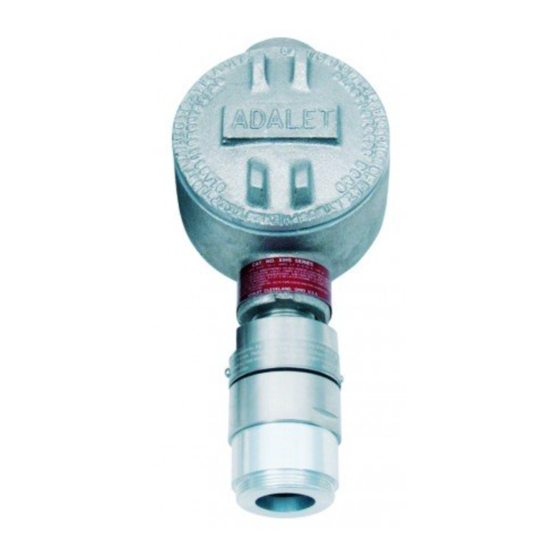
Page 6: Description
The flame arrestor guard protects the flame arrestor from impact damage. Four color-coded leads extend from the top of the detector. The leads allow you to connect the detector to the amplifier. 2 • 65-2405RK-05 Combustible Gas Transmitter 1.800.561.8187 information@itm.com www. -
Page 7: Amplifier
Consult RKI Instruments, Inc. if you plan to change the calibration gas for the transmitter, for example from a methane calibration to a hexane calibration. The amplifier includes the detector terminal strip, controller terminal strip, span pot, zero pot, and test points (see Figure 1). -
Page 8: Installation
Reducing Bushing LEL Detector Figure 2: Mounting the Combustible Gas Transmitter At the monitoring site you select, hang or mount the junction box with the detector facing down (see Figure 2). 4 • 65-2405RK-05 Combustible Gas Transmitter 1.800.561.8187 information@itm.com www. .com... -
Page 9: Wiring The Combustible Gas Transmitter
The power cable may disrupt the transmission of the transmitter signal to the controller. 11. Connect the wires to the applicable detector/transmitter terminal strip at the controller as shown in Figure 3. 65-2405RK-05 Combustible Gas Transmitter • 5 1.800.561.8187 information@itm.com www. - Page 10 12. If shielded cable is used, connect the cable’s drain wire to an available chassis (earth) ground at the controller. RKI controllers typically have a ground stud that can be used to ground the cable’s drain wire. 6 • 65-2405RK-05 Combustible Gas Transmitter 1.800.561.8187 information@itm.com www.
-
Page 11: Startup
If necessary, use a small flat-blade screwdriver to adjust the zero pot until the voltmeter reading is 100 mV (±2 mV). Remove the voltmeter leads from the test points. Secure the junction box cover to the junction box. 65-2405RK-05 Combustible Gas Transmitter • 7 1.800.561.8187 information@itm.com www. -
Page 12: Maintenance
Set a voltmeter to read in the millivolt (mV) range. Plug the voltmeter leads into the test points on the amplifier. Plug the positive lead into the red (+) test point; plug the negative lead into the black (-) test point. 8 • 65-2405RK-05 Combustible Gas Transmitter 1.800.561.8187 information@itm.com www. -
Page 13: Troubleshooting
NOTE: This troubleshooting guide describes transmitter problems only. See the controller operator’s manual for problems you may encounter with the controller. 65-2405RK-05 Combustible Gas Transmitter • 9 1.800.561.8187 information@itm.com www. -
Page 14: Replacing Components Of The Combustible Gas Transmitter
If necessary for environmental conditions, apply thread sealant or teflon tape to the hub and/or detector threads to seal them. 10 • 65-2405RK-05 Combustible Gas Transmitter 1.800.561.8187 information@itm.com www. - Page 15 Install the detector and controller terminal strips into their sockets on the new amplifier as shown in Figure 3 on page 6 of this manual. If controller leads or detector leads were removed during this procedure, refer to Table 4 and Table 5 below. 65-2405RK-05 Combustible Gas Transmitter • 11 1.800.561.8187 information@itm.com www.
-
Page 16: Calibration Frequency
3 to 6 months is adequate for most combustible gas transmitter applications. Unless experience in a particular application dictates otherwise, RKI Instruments, Inc. recommends a calibration frequency of every 3 months. If an application is not very demanding, for example detection in a clean, temperature... -
Page 17: Calibration
Screw the regulator into the zero air calibration cylinder. Use the calibration kit sample tubing to connect the regulator to the calibration cup. Turn the regulator’s on/off knob counterclockwise to open the regulator. 65-2405RK-05 Combustible Gas Transmitter • 13 1.800.561.8187 information@itm.com www. -
Page 18: Setting The Response Reading
When the controller display reading falls below the alarm setpoints, return the controller to normal operation. Verify that the controller display reading decreases and stabilizes at 0 %LEL. Store the components of the calibration kit in a safe and convenient place. 14 • 65-2405RK-05 Combustible Gas Transmitter 1.800.561.8187 information@itm.com www. -
Page 19: Parts List
Combustible gas detector, CSA type 65-2405RK-05 Combustible gas transmitter (includes detector and amplifier; specify target gas when ordering) 71-0180RK 65-2405RK-05 Combustible Gas Transmitter Operator’s Manual (this docu- ment) 81-0002RK-01 Steel calibration cylinder, 50% LEL hydrogen in air, 34-liter 81-0007RK-01 Steel calibration cylinder, 15% LEL hexane in air, 34-liter...


Need help?
Do you have a question about the 65-2405RK-05 and is the answer not in the manual?
Questions and answers