
Subscribe to Our Youtube Channel
Related Manuals for RKI Instruments 65-2434RK


Summary of Contents for RKI Instruments 65-2434RK
- Page 1 65-2434RK Carbon Monoxide Transmitter Operator’s Manual Part Number: 71-0061RK Revision: D Released: 2/16/11 1.800.561.8187 information@itm.com www. .com...
- Page 2 Typical calibration frequencies for most applications are between 3 and 6 months, but can be required more often or less often based on your usage. 65-2434RK CO Transmitter 1.800.561.8187 information@itm.com www.
- Page 3 Product Warranty RKI Instruments, Inc. warranties gas alarm equipment sold by us to be free from defects in materials, workmanship, and performance for a period of one year from date of shipment from RKI Instruments, Inc. Any parts found defective within that period will be repaired or replaced, at our option, free of charge.
-
Page 4: Table Of Contents
Parts List ..............13 65-2434RK CO Transmitter 1.800.561.8187... -
Page 5: Overview
90% in 30 seconds WARNING: When using the 65-2434RK, you must follow the instructions and warnings in this manual to assure proper and safe operation of the 65-2434RK and to minimize the risk of personal injury. Be sure to maintain and periodically calibrate the 65-2434RK as described in this manual. -
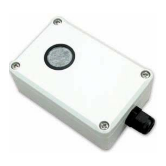
Page 6: Description
(that is proportional to the detection range) and transmits the signal to a gas monitoring controller. The amplifier PCB includes the interconnect terminal strip, sensor sockets, span pot, zero pot, and test points (see Figure 1). 2 • 65-2434RK CO Transmitter 1.800.561.8187 information@itm.com www. -
Page 7: Enclosure
Use the enclosure’s two mounting holes, accessible with the cover removed, to mount the CO transmitter to a vertical surface at the monitoring site. Use the cover on the front of the enclosure to access the interior of the enclosure. 65-2434RK CO Transmitter • 3 1.800.561.8187 information@itm.com www. -
Page 8: Installation
At the monitoring site, use #6 screws through the enclosure’s two mounting holes to secure it to a vertical surface. Secure the cover to the enclosure with the four cover screws. 4 • 65-2434RK CO Transmitter 1.800.561.8187 information@itm.com www. -
Page 9: Wiring The Co Transmitter To A Controller
Figure 3 below. Controller or Recording Device CAL+ + (10 VDC - 30 VDC) ZERO 4 - 20 mA In (FB) CAL- SPAN Figure 3: Wiring the CO Transmitter to a Controller 65-2434RK CO Transmitter • 5 1.800.561.8187 information@itm.com www. .com... -
Page 10: Startup
The procedure below describes applying zero emission air, usually called zero air, using a calibration kit that includes a calibration cup, calibration gas, sample tubing, and a fixed flow regulator with an on/off knob. RKI Instruments, Inc. recommends using a 0.5 LPM (liters per minute) fixed flow regulator. -
Page 11: Maintenance
Use the following formula to determine the correct test points output for the test sample. Output (mV) = (calibrating sample/fullscale) X 400 + 100 For example, with a test sample of 50 PPM CO and a fullscale setting of 65-2434RK CO Transmitter • 7 1.800.561.8187 information@itm.com www. -
Page 12: Troubleshooting
Calibrate the transmitter. • If the fail condition continues, replace the CO sensor. • If the fail condition continues, contact RKI for further instruction. Slow or No Response/Difficult or Unable to Calibrate 8 • 65-2434RK CO Transmitter 1.800.561.8187 information@itm.com www. .com... -
Page 13: Replacing Components Of The Co Transmitter
Verify that the calibration cylinder contains an adequate supply of a fresh test sample. If the calibration/response difficulties continue, replace the CO sensor as described later in this section. If the calibration/response difficulties continue, contact RKI Instruments, Inc. for further instruction. Replacing Components of the CO Transmitter This section includes procedures to replace the CO sensor, amplifier PCB, and charcoal filter. - Page 14 Remove the enclosure’s cover by unscrewing the four cover screws, one at each corner. Unplug the CO sensor from the amplifier PCB. Remove the rubber boot that secures the charcoal filter to the CO sensor. 10 • 65-2434RK CO Transmitter 1.800.561.8187 information@itm.com www.
-
Page 15: Calibration Frequency
Remove the enclosure cover, then plug the voltmeter leads into the test points on the amplifier PCB. Plug the positive lead into the test point labeled CAL+; plug the negative lead into the test point labeled CAL-. 65-2434RK CO Transmitter • 11 1.800.561.8187 information@itm.com www. -
Page 16: Setting The Zero Reading
Turn the regulator’s on/off knob clockwise to close it. Remove the calibration cup from the sensor face. Unscrew the regulator from the calibration cylinder. NOTE: For convenience, leave the components of the calibration kit connected by the sample tubing. 12 • 65-2434RK CO Transmitter 1.800.561.8187 information@itm.com www. .com... -
Page 17: Returning To Normal Operation
Filter (charcoal) 57-0035RK-01 Amplifier PCB, CO 65-2434RK CO transmitter, complete 71-0061RK 65-2434RK CO Transmitter Manual (this document) 81-0064RK Calibration cylinder (50 PPM CO in air; 34 liter) 81-0076RK-01 Zero air calibration cylinder (34 liter) 81-1050RK Regulator with gauge and knob, 0.5 LPM, for 17 liter and 34 liter...
Need help?
Do you have a question about the 65-2434RK and is the answer not in the manual?
Questions and answers