Table of Contents
Advertisement
Quick Links
Clamp Meter
Analog Technologies
317 and 319
FEATURES
Digital Display: 6000 count resolution
Low Battery Indication: Display when the batteries are
below their required voltage
Power Source: Three AAA IEC LR03 batteries
Clamp Opening Size: 1.45"
Jaw Diameter: 1.45"
Dimension (L×W×H): 6.39"×2.29"×1.20"
Auto Range: Available in Ohms
Safety: CE
EN/IEC 61010-1 and IEC 61010-2-032
Measurement Category: 600 V CAT Ⅲ
Figure 1. The Photo of Actual 317
Weight: About 384g
APPLICATIONS
It's widely used to measure alternating voltage, direct
voltage, current, capacitance, diode, audion, resistance,
temperature, frequency, etc.
DESCRIPTION
The 317 and 319 are hand-held and battery-operated clamp
meters that can measure AC current, DC current, AC voltage,
DC voltage, resistance, continuity and frequency.
The clamp meter is battery powered with a digital display.
Except where noted, the descriptions and instructions in this
datasheet apply to both the 317 and 319 clamp meters.
Warning: To avoid possible electric shock or
personal injury, read "Safety Information" before using
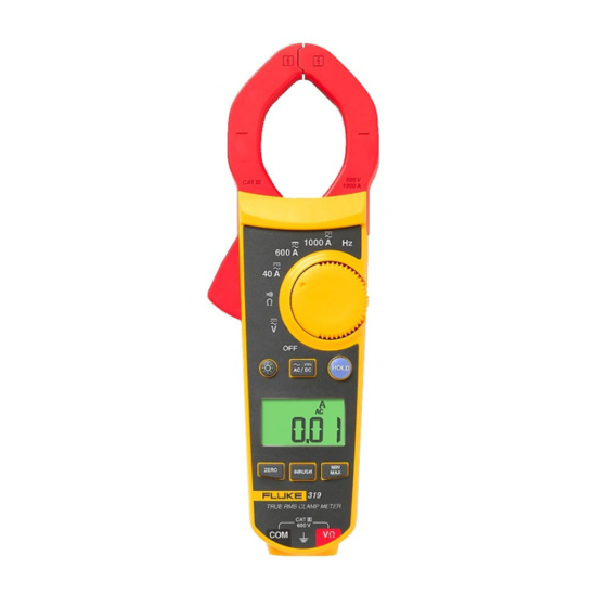
Figure 2. The Photo of Actual 319
the clamp meter.
SAFETY INFORMATION
Use the clamp meter only as specified in this datasheet,
otherwise the protection provided by the clamp meter may be
impaired.
Adhere to local and national safety codes. Individual
protective equipment must be used to prevent shock and arc
blast injury where hazardous live conductors are exposed.
Use extreme caution when working around bare conductors
or bus bars. Contact with the conductor could result in
electric shock.
Use caution when working with voltages above 30V AC rms,
42V AC peak, or 60V DC. These voltages pose a shock
hazard.
Figure 3. The Photo of Actual 319
Never measure current while the test leads are inserted into
the input jacks.
Do not use the clamp meter in wet, dirty or hazardous
2352 Walsh Ave. Santa Clara, CA 95051. U. S. A. Tel.: (408) 748-9100, Fax: (408) 748-9111 www.analogtechnologies.com
1
Copyrights 2000 – 2012, Analog Technologies, Inc. All Rights Reserved. Updated on 11/22/2012
Advertisement
Table of Contents

Related Manuals for Fluke 317


Summary of Contents for Fluke 317
- Page 1 The clamp meter is battery powered with a digital display. Except where noted, the descriptions and instructions in this datasheet apply to both the 317 and 319 clamp meters. Warning: To avoid possible electric shock or personal injury, read “Safety Information” before using Figure 2.
- Page 2 Clamp Meter Analog Technologies 317 and 319 environment. Do not use the clamp meter or test leads if either appears measurements. damaged. Inspect the clamp meter and test leads before Do not apply more than the rated voltage, as marked on using.
-
Page 3: General Specifications
Clamp Meter Analog Technologies 317 and 319 Volts DC Conforms to applicable European directives. For measurements performed in the building installations such as distribution panels, feeders CAT Ⅲ and short branch circuits and lighting systems in large buildings. Do not dispose of this product as unsorted municipal waste. - Page 4 Clamp Meter Analog Technologies 317 and 319 (V ac) Resolution 0.1V Accuracy 1.5%±5 digit (20-500Hz) AC response Range 600.0V Resolution 0.1V (V dc) Accuracy 1%±4 digit 400.0Ω Range 4000Ω Ω 0.1Ω Resolution 1Ω Accuracy 1%±5 digit ≤ 30Ω Inrush Integration time...
-
Page 5: Meter Function
Clamp Meter Analog Technologies 317 and 319 0.1× (specified accuracy)/℃ Temperature Coefficients (<64℉ or >82℉) (<18℃ or >28℃) METER FUNCTION Table 4. ○ Current sensing clamp Tactile barrier ○ Warning: To avoid injury, do not hold the clamp meter anywhere above the tactile barrier. -
Page 6: Taking Measurements
Clamp Meter Analog Technologies 317 and 319 ○ Jaw release Alignment marks: to meet accuracy specifications the conductor must be aligned with ○ the marks. Table 5. Rotary Switch Switch Position Function Clamp meter is powered down DC and AC voltage... -
Page 7: Measuring Ac Or Dc Current
Clamp Meter Analog Technologies 317 and 319 When making current measurements, disconnect the test leads from the clamp meter. Keep fingers behind Tactile Barrier. See table 4. Note When measuring current, center the conductor in the clamp using the alignment marks on the clamp. See table 4. -
Page 8: Measuring Resistance
Clamp Meter Analog Technologies 317 and 319 When making electrical connectors, connect the common test lead before connecting the live test lead; when disconnecting, disconnect the live test lead before disconnecting the common test lead. When using test probes, keep fingers behind the finger guards. -
Page 9: Testing Continuity
Clamp Meter Analog Technologies 317 and 319 Figure 8. Measuring Resistance TESTING CONTINUITY Warning To avoid electrical shock when testing continuity in a circuit, make sure the power to the circuit is turned off and all capacitors are discharged. To test continuity: 1. - Page 10 Clamp Meter Analog Technologies 317 and 319 MEASURING CURRENT FREQUENCY (319 ONLY) To measure current frequency: 1. Turn the rotary switch to Hz. 2. Open the clamp by pressing the jaw release and insert the conductor to be measured into the clamp.
-
Page 11: Maintenance
Clamp Meter Analog Technologies 317 and 319 AUTO POWER OFF The clamp meter turns of if there is no button pushed or rotary function switch operation for 20 minutes. Turn the clamp meter off and on to restart the clamp meter. This feature is disabled in MIN, MAX and HOLD modes; it can also be disabled for all modes by holding while turning the clamp meter on. - Page 12 Clamp Meter Analog Technologies 317 and 319 Customers are responsible for their applications using ATI components. In order to minimize risks associated with the customers’ applications, adequate design and operating safeguards must be provided by the customers to minimize inherent or procedural hazards.
Need help?
Do you have a question about the 317 and is the answer not in the manual?
Questions and answers