Table of Contents
Advertisement
Quick Links
These instructions apply only for the destination countries listed on the appliance's data plate.
This is a class 3 built in hob.
We advise you to read this manual carefully, which contains all the instructions for
maintaining the appliance's aesthetic and functional qualities.
For further information on the product: www.smeg.com
Contents
28
28
31
31
32
32
32
33
33
34
34
35
35
35
36
38
38
38
40
40
40
41
42
42
45
50
27
Advertisement
Table of Contents

Subscribe to Our Youtube Channel
Related Manuals for Smeg PV175CND


Summary of Contents for Smeg PV175CND
-
Page 1: Table Of Contents
These instructions apply only for the destination countries listed on the appliance's data plate. This is a class 3 built in hob. We advise you to read this manual carefully, which contains all the instructions for maintaining the appliance's aesthetic and functional qualities. For further information on the product: www.smeg.com... -
Page 2: Instructions
Instructions 1 Instructions • Cleaning and maintenance must not be carried out by 1.1 General safety instructions unsupervised children. Risk of personal injury • Make sure that the flame- spreader crowns are correctly • During use the appliance and its positioned in their housings with accessible parts become very hot. - Page 3 Instructions • Switch off the appliance • Do not spray any spray products immediately after use. near the oven. • Do not modify this appliance. • Do not use plastic cookware or containers when cooking food. • Do not try to repair the appliance yourself or without the intervention •...
- Page 4 Instructions Installation • Installation using a hose must be carried out so that the length of • This appliance must not be the hose does not exceed 2 metres installed in a boat or caravan. when fully extended for steel •...
-
Page 5: Appliance Purpose
Instructions For this appliance 1.2 Appliance purpose • This appliance is intended for • The glass ceramic surface is cooking food in the home highly resistant to impact. environment. Every other use is However, prevent hard, solid considered improper. objects from falling on the cooking surface as they may •... -
Page 6: Identification Plate
Instructions 1.6 How to read the user manual Our appliances are packed in non- polluting and recyclable materials. This user manual uses the following reading • Consign the packing materials to the conventions: appropriate selective collection centres. Instructions Plastic packaging General information on this user Danger of suffocation manual, on safety and final... -
Page 7: Description
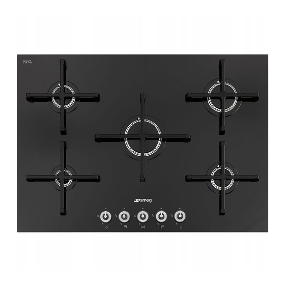
Description 2 Description 2.1 General Description 60 cm 70 cm AUX = Auxiliary R1= Large rapid SR = Semi-rapid R2 = Medium rapid RR = Reduced rapid... -
Page 8: Symbols
Description 2.2 Symbols 2.3 Available accessories Cooking zones Burner wrench (for installer only) Front left Rear left Central Rear right Front right Centre left Burner knobs For removing and replacing the hob burners. Supplied and optional accessories can be requested to Authorised Useful for lighting and adjusting the hob Assistance Centres. -
Page 9: Use
3 Use Improper use 3.1 Instructions Risk of damage to surfaces Improper use Danger of burns • Do not use aluminium foil to cover the burners or hob body. • Make sure that the flame-spreader • The cooking vessels or griddle plates crowns are correctly positioned in their should be placed inside the perimeter of housings with their respective burner... -
Page 10: Using The Hob
3.3 Using the hob Correct positioning of the grids The grids over the burners must be All the appliance's control and monitoring positioned in parallel to the control panel, devices are located together on the front not perpendicular. panel. The burner controlled by each knob is shown next to the knob. - Page 11 Practical tips for using the hob Using a griddle For better burner efficiency and to minimise A few precautions are necessary if you wish gas consumption, use pans with lids and of to use a griddle: suitable size for the burner, so that flames •...
-
Page 12: Cleaning And Maintenance
Cleaning and maintenance 4 Cleaning and maintenance Ordinary daily cleaning Always use only specific products that do 4.1 Instructions not contain abrasives or chlorine-based acids. Improper use Pour the product onto a damp cloth and Risk of damage to surfaces wipe the surface, rinse thoroughly and dry with a soft cloth or a microfibre cloth. - Page 13 Cleaning and maintenance Cooking hob grids Igniters and thermocouples Remove the grids and clean them with For correct operation the igniters and lukewarm water and non-abrasive thermocouples must always be perfectly detergent. Make sure to remove any clean. Check them frequently and clean encrustations.
-
Page 14: Installation
Installation 5 Installation 5.2 Section cut from the work surface The following operation requires 5.1 Safety instructions building and/or carpentry work Heat production during appliance and must therefore be carried out operation by a competent tradesman. Risk of fire Installation can be carried out on various materials such as masonry, •... -
Page 15: Mounting
Installation 5.3 Mounting Over empty kitchen unit or drawers If there are other pieces of furniture (lateral Over built-in oven walls, drawers, etc.), dishwashers or fridges The distance between the hob and the under the hob, a double-layer wooden kitchen furniture or other installed base must be installed at least 10 mm from appliances must be enough to ensure the bottom of the hob to avoid any... -
Page 16: Fixing Brackets
Installation 5.5 Gas connection Hob seal To prevent leakage of liquid between the Gas leak frame of the hob and the work surface, Danger of explosion place the adhesive seal provided along the entire outer edge of the hob before •... - Page 17 Installation Carefully screw the connector 3 to the gas Connection to LPG connector 1 of the appliance, placing the Use a pressure regulator and make the seal 2 between them. connection on the gas cylinder following the guidelines set out in the regulations in force.
- Page 18 Installation Extraction of the combustion products 1 Extraction using a hood 2 Extraction without a hood The combustion products may be extracted by means of hoods connected to a natural draught chimney whose efficiency is certain A Single natural draught chimney or via forced extraction.
-
Page 19: Adaptation To Different Types Of Gas
Installation 5.6 Adaptation to different types of 3. Pull the knobs upwards to remove them. The appliance is preset for natural gas G20 (2H) at a pressure of 20 mbar. If other types of gas are to be used, the nozzles must be replaced and the primary air must be adjusted. - Page 20 Installation 5. Remove the top. 3. Adjust the air flow by moving the air regulator B to obtain the distance D given in the relevant table (see “Gas types and Countries”). 4. After adjusting each burner, reassemble the appliance correctly. Adjusting the minimum setting for natural or city gas Light the burner and turn it to the minimum...
- Page 21 Installation Adjusting the minimum setting for LPG Tighten the screw located at the side of the tap rod clockwise all the way. Following adjustment to a gas other than the one originally set in the factory, replace the gas setting label fixed to the appliance with the one corresponding to the new gas.
- Page 22 Installation Gas types and Countries Gas types GB-IE FR-BE DE 1 Natural Gas G20 20 mbar • • • • • • • • • G20/25 20/25 mbar • 2 Natural Gas G25 • 25 mbar 3 Natural Gas G25 20 mbar •...
- Page 23 Installation Burner and nozzle characteristics tables Natural Gas G20 Rated heating capacity (kW) Nozzle diameter (1/100 mm) Reduced capacity (W) 1050 1050 Primary air (mm) Natural Gas G25 Rated heating capacity (kW) Nozzle diameter (1/100 mm) Reduced capacity (W) 1050 1050 Primary air (mm) Natural Gas G25...
-
Page 24: Electrical Connection
Installation 5.7 Electrical connection The appliance can work in the following modes: Power voltage • 220-240 V 1N~ Danger of electrocution 220-240V~ 1 mm • Have the electrical connection performed by authorised technical personnel. 20 mm • Use personal protective equipment. Use a 3 x 1 mm²...
Need help?
Do you have a question about the PV175CND and is the answer not in the manual?
Questions and answers