Table of Contents
Advertisement
Quick Links
Advertisement
Table of Contents
Troubleshooting

Related Manuals for Tru-Weld TW5700


Summary of Contents for Tru-Weld TW5700
- Page 1 TRU-WELD Stud Welding TW5700 Stud Welding System Operations Manual...
-
Page 2: Table Of Contents
Safety Precautions - Electric Shock and Arc Rays Safety Precautions - Welding Sparks and EMF’s TW5700 Product Specifications TW5700 Setup and Installation - Initial Steps TW5700 Setup and Installation - Power Diagrams TW5700 Setup and Installation - Primary Power Stud Gun Setup - Initial Steps... -
Page 3: Warranty Information
TRU-WELD will be at the customer’s expense. At the option of TRU-WELD the defect will either be repaired or replaced. Notice must be provided to TRU-WELD of a warranty defect within 30 days that the defect or failure is incurred. -
Page 4: Company Profile And Product Information
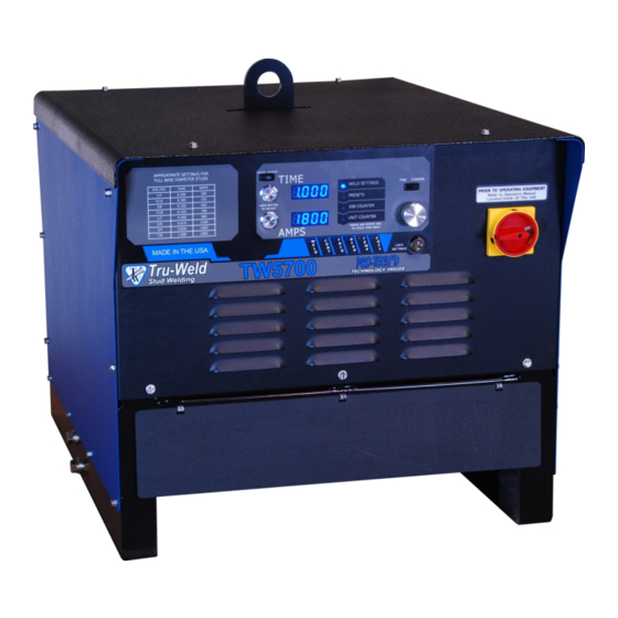
Product Information The TW5700 is a fully integrated 1900A stud welding system designed to be a perfect fit for shop use, excelling at small- to medium-sized diameter studs, all in a compact, affordable package. -
Page 5: Safety Precautions - Symbols And Fumes
Do not install, operate, or repair the TW5700 welding equipment without reading this manual and all safety precautions stated within! The TW5700 was designed and built with operator safety in mind. Every effort has been made to protect the trained operator from injury. Familiarization with the information in this manual is to minimize the risk of shock or injury. -
Page 6: Safety Precautions - Electric Shock And Arc Rays
Stud Welding Safety Precautions ELECTRIC SHOCK Electric shock can injure or kill! Precautionary measures must be taken to provide maximum protection against electrical shock Do not touch live or energized electrical parts or store metallic objects near power Ground the work or metal to be welded to a good electrical (earth) ground ... -
Page 7: Safety Precautions - Welding Sparks And Emf's
Stud Welding Safety Precautions WELDING SPARKS Heat from flames and arcs can start fires. Hot slag or sparks can also cause fires and explosions. Remove all combustible materials from the work area or cover these materials with a protective non-flammable tarp. Combustible materials include wood, fabrics, sawdust, liquid and gas fuels, solvents, paints and coatings, paper, etc. -
Page 8: Tw5700 Product Specifications
TW5700 Product Specifications Weld Range 1/4” to 7/8” Consistent welding regardless of stud diameter Duty Cycle 1/4” thru 3/8” Unlimited 1/2” 22 to 24 per minute 5/8” 9 to 10 per minute 3/4” 4 to 5 per minute 7/8” 3 to 4 per minute... -
Page 9: Tw5700 Setup And Installation - Initial Steps
The welding power source is designed to be operated from three-phase, 60Hertz, AC power supply. Consult the local electrical utility supplier if there are any questions on the electrical system at the present installation site. The TW5700 should be operated from a separate, fused or circuit-breaker protected circuit. -
Page 10: Tw5700 Setup And Installation - Power Diagrams
Power Connection Diagrams Electrical Input Requirements The TW5700 is equipped with an input voltage jumper block so the unit can be operated with different line voltages depending on the supplied voltage. The jumper setting should be checked to see if they are properly positioned for the voltage being used. -
Page 11: Tw5700 Setup And Installation - Primary Power
Do not touch electrically hot parts Primary Power Cable and Ground Connection Remove the top cover of the TW5700 Route the primary power cable through the power inlet hole in the top left corner on the backside of the welder with enough slack to reach the terminal... -
Page 12: Stud Gun Setup - Initial Steps
Stud Gun Setup TWE17000 Gun Setup Each stud welding application requires that the stud gun be set up properly for the correct stud and ferrule arrangement. Select the correct style and size of chuck and attach it to the stud gun ... -
Page 13: Stud Gun Setup - Lift Adjustment
Stud Gun Setup Lift: Set the lift when all of the accessories and stud have been properly set on the stud gun and prior to welding. Plug the stud gun control connector directly into the stud welder (do not attach the weld cable). Turn on the stud welder and actuate the trigger of the stud gun with the stud and ferrule in place. -
Page 14: Stud Gun Setup - Free Travel Adjustment And Weld Preparation
Stud Gun Setup Free Travel Adjustment This adjustment can be used to control the force with which the stud is plunged into the molten weld pool by moving the engagement point of when the shaft of the stud gun engages the damp- ener. -
Page 15: Cable Connection - Ground Cable Connections
TW5700 Cable Connection Ground Cable Connections The TW5700 is equipped with one ground cable connection located beneath the access panel on the front of the machine Tighten the ground cable to the bracket and secure the heavy duty C-clamp to the work... -
Page 16: Cable Connection - Weld Cable Connections
TW5700 Cable Connection Weld Cable Connections The TW5700 has one weld and control cable connection on the front of the welder behind the access panel Tighten the weld cable lug to the weld cable bracket labeled weld cable ... -
Page 17: Machine Operation - Powering On And Control Panel
TW5700 Operation TW5700 Power Switch/Power On The power switch for the TW5700 is located on the right front of the welder’s control panel. Off position is verti- cal with the “O” showing. On position is horizontal with the “I” displayed. -
Page 18: Machine Operation - Menu Selection
TW5700 Operation Menu Selection By depressing the adjustment dial and rotating clockwise or counter clockwise a menu can be chosen. The menus include weld settings, welding presets, job counter, and a lifetime unit counter. Menu options Adjustment dial Supervisor lock Menu Selection: 1. -
Page 19: Machine Operation - Time And Current Settings
TW5700 Operation Weld Settings - Time and Current The time and current controls are located on the front of the welder. The controls consist of a time button, current button, adjustment dial, fine/coarse switch, and a supervisor lock. The digital display will indicate the settings chosen during setup. -
Page 20: Machine Operation - Preset Menu
TW5700 Operation Preset Menu The full range of studs the machine is capable of welding is preloaded onto the unit for fast and easy access. Any combination of time and current can also be saved to a programmable preset location. -
Page 21: Machine Operation - Stud Counters
TW5700 Operation Weld Counter and Weld Counter Reset The TW5700 is equipped with two different counters to display the number of times the unit has drawn an arc. Job Counter (Resettable) - Is a running total of the number of welds since the coun- ter was last reset. -
Page 22: Suggested Time And Current Settings
TW5700 Suggested Weld Settings Suggested Settings (Full Base Diameter Studs) -
Page 23: Welding - Step By Step Process
Visually inspect weld. Note - when determining finished length required for the particular application, keep in mind the reduction in length (burn-off) from stud welding operations. TRU-WELD stud lengths are always given before weld. -
Page 24: Welding Hints And Suggestions
TW5700 Welding Hints and Suggestions Stud Welding • Keep weld studs and ferrules clean and dry • Set the time for the appropriate weld base diameter (see chart on page 20) • Set the amperage for the appropriate weld base diameter (see chart on page 20) •... -
Page 25: Weld Inspection - Visual Inspection
TW5700 Weld Inspection Visual Weld Inspection and Adjustments - After shooting the stud, break away ferrule and visually inspect the weld. Good Weld A good weld will have a smooth and even fillet with a blue-silver tint. Partial Weld A partial weld will result in a collar that does not extend around the entire diameter of the stud base. -
Page 26: Tw5700 Troubleshooting
Thermostat circuit A fault in the thermostatic circuit will cause the fan to run not cycle on/off) continuously, call a local TRU-WELD rep. for repairs Unit turns on, coil boot test is Bad connection or 1. Test control cable by plugging weld tool directly into unit... -
Page 27: Tw5700 Troubleshooting
Perform routine gun maintenance or replace gun if needed Note - Always turn off power to the welder before working on or testing components within the welder. Contact a TRU-WELD representative for replacement parts and for servicing welding equipment. -
Page 28: Tw5700 Troubleshooting
TW5700 Troubleshooting Circuit board, control box, fuse, breaker and L.E.D. layout Board 16000 16001 16002 B16001 16060 Name Digital Control Pilot Arc Touch / Trigger Gun Control Dual Gate Drive Gun Control Accessory LED 1 L1- Gate Power GPri - SSR1... -
Page 29: Parts And Accessories
TW5700 Parts and Accessories Closed Ferrule Grips (1” Long) Brass Split Ferrule Grip (1” Long) Brass Stud Diameter Part Number Stud Diameter Part Number 3/4” GN-075 3/4” GC-075 7/8” GN-087 7/8” GC-087 1” GN-100 1” GC-100 Adjustable Chucks Headed Chucks... - Page 30 TRU-WELD Stud Welding Equipment Division 6400 N. Honeytown Road Smithville, Ohio 44677 (330) 725-7744 Phone (330) 669-2473 Fax TWE@tfpcorp.com http://truweldstudwelding.com Version 1 02/01/2019...
Need help?
Do you have a question about the TW5700 and is the answer not in the manual?
Questions and answers