
Related Manuals for Tru-Weld TWI4200


Summary of Contents for Tru-Weld TWI4200
- Page 1 TRU-WELD Stud Welding TWi4200 Stud Welding System Operations Manual (800) 321-5588 Phone Tru-Fit Products/Tru-Weld truweld@tfpcorp.com 460 Lake Road www.tfpcorp.com Medina, Ohio 44256 www.truweldstudwelding.com...
-
Page 2: Warranty Information
TRU-WELD will be at the customer’s expense. At the option of TRU-WELD the defect will either be repaired or replaced. Notice must be provided to TRU-WELD of a warranty defect within 30 days that the defect or failure is incurred. -
Page 3: Product Information
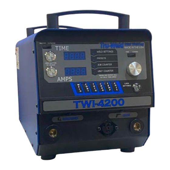
The TWI4200 is a fully integrated 600A single phase 115v stud welding system for ferrule-shielded drawn arc stud welding. The TWI4200 contains digital controls for weld time & weld current. The system was designed to be a perfect fit for shop use without needing access to three phase power and is capable of welding up to 3/8"... - Page 4 Do not install, operate, or repair the TWI4200 welding equipment without reading this manual and all safety precautions stated within! The TWI4200 was designed and built with operator safety in mind. Every effort has been made to protect the trained operator from injury. Familiarization with the information in this manual is to minimize the risk of shock or injury.
-
Page 5: Electric Shock
Stud Welding Safety Precautions ELECTRIC SHOCK Electric shock can injure or kill! Precautionary measures must be taken to provide maximum protection against electrical shock Do not touch live or energized electrical parts or store metallic objects near power Ground the work or metal to be welded to a good electrical (earth) ground ... -
Page 6: Welding Sparks
Stud Welding Safety Precautions WELDING SPARKS Heat from flames and arcs can start fires. Hot slag or sparks can also cause fires and explosions. Remove all combustible materials from the work area or cover these materials with a protective non-flammable tarp. Combustible materials include wood, fabrics, sawdust, liquid and gas fuels, solvents, paints and coatings, paper, etc. - Page 7 TWI4200 Product Specifications Weld Range 14ga to 3/8" Consistent welding regardless of stud diameter Duty Cycle Up to 1/4" 3/8" Dimensions 14.5"(368mm) Height Width 11.3” (287mm) 22.5”(572mm) Length 60 Lbs. (27kg) Weight Input Voltages 115 VAC Single-Phase 50/60 Fusing Requirements...
-
Page 8: Electrical Input Requirement
The welding power source is designed to be operated from 115V / 15A, Consult the local electrical utility supplier if there are any questions on the electrical system at the present installation site. The TWI4200 should be operated from a separate, fused or circuit-breaker protected circuit. - Page 9 Stud Gun Setup TWE19000Gun Setup Each stud welding application requires that the stud gun be set up properly for the cor- rect stud and ferrule arrangement. Select the correct style and size of chuck and attach it to the stud gun ...
-
Page 10: Adjusting The Lift
Stud Gun Setup Lift: Set the lift when all of the accessories and stud have been properly set on the stud gun and prior to welding. Plug the stud gun control connector directly into the stud welder (do not attach the weld cable). Turn on the stud welder and actuate the trigger of the stud gun with the stud and ferrule in place. - Page 11 Stud Gun Setup Free Travel Adjustment This adjustment can be used to control the force with which the stud is plunged into the molten weld pool by moving the engagement point of when the shaft of the stud gun engages the damp- ener.
-
Page 12: Ground Cable Connections
♦ then secure the C-clamp to the work surface Ground connection Weld Cable Connections The TWI4200 has one weld and control cable connection on the bottom right of ♦ the welder. ♦ Tighten the weld cable to the machine by rotating the connector clockwise Plug the male control cable connector to the female panel mount labeled ♦... - Page 13 TWI4200 Operation TWI4200 Power Switch/Power On The power switch for the TWI4200 is located on the right rear of the welder. Off position is marked with the “O” showing. On position is marked with the “I” displayed. When the welder is turned on, the digital display will go through a self-diagnostic check.
-
Page 14: Menu Selection
TWI4200 Operation Menu Selection By depressing the adjustment dial and rotating clockwise or counter clockwise a menu can be chosen. The menus include weld settings, welding presets, job counter, and a lifetime unit counter. Menu options Adjustment dial Supervisor lock Menu Selection: 1. - Page 15 TWI4200 Operation Weld Settings - Time and Current The time and current controls are located on the front of the welder. The controls consist of a time button, current button, adjustment dial, fine/coarse switch, and a supervisor lock. The digital display will indicate the settings chosen during setup.
-
Page 16: Preset Menu
TWI4200 Operation Preset Menu The full range of studs the machine is capable of welding is preloaded onto the unit for fast and easy access. Any combination of time and current can also be saved to a programmable preset location. - Page 17 TWI4200 Operation Weld Counter and Weld Counter Reset The TWI4200 is equipped with two different counters to display the number of times the unit has drawn an arc. Job Counter (Resettable) - Is a running total of the number of welds since the coun- ter was last reset.
- Page 18 Visually inspect weld. Note - when determining finished length required for the particular application, keep in mind the reduction in length (burn-off) from stud welding operations. TRU-WELD stud lengths are always given before weld.
-
Page 19: Stud Welding
TWI4200 Welding Hints and Suggestions Stud Welding • Keep weld studs and ferrules clean and dry • Set the time for the appropriate weld base diameter (see chart on page 20) • Set the amperage for the appropriate weld base diameter (see chart on page 20) •... - Page 20 TWI4200 Weld Inspection Visual Weld Inspection and Adjustments - After shooting the stud, break away ferrule and visually inspect the weld. Good Weld A good weld will have a smooth and even fillet with a blue-silver tint. Partial Weld A partial weld will result in a collar that does not extend around the entire diameter of the stud base.
- Page 21 TWI4200 Troubleshooting Problem Possible Cause 1. Check power at the wall. Unit will not turn on No power 2. Check circuit breaker on back of unit. 3. Make these checks before contacting a TWE Rep Charge LED does not come on Circuit Board failure 1.
- Page 22 Perform routine gun maintenance or replace gun if needed Note - Always turn off power to the welder before working on or testing components within the welder. Contact a TRU-WELD representative for replacement parts and for servicing welding equipment.
- Page 23 TRU-WELD 460 Lake Road Medina, Ohio 44256 (800) 321-5588 Phone truweld@tfpcorp.com truweldstudwelding.com Tru-Fit Products (800) 321-5588 460 Lake Rd, Medina, OH 44256 Version 1 05/28/2024...
Need help?
Do you have a question about the TWI4200 and is the answer not in the manual?
Questions and answers