Table of Contents
Advertisement
Quick Links
TWE - SC1100
Drawn Arc Gas Short Cycle
Operations Manual
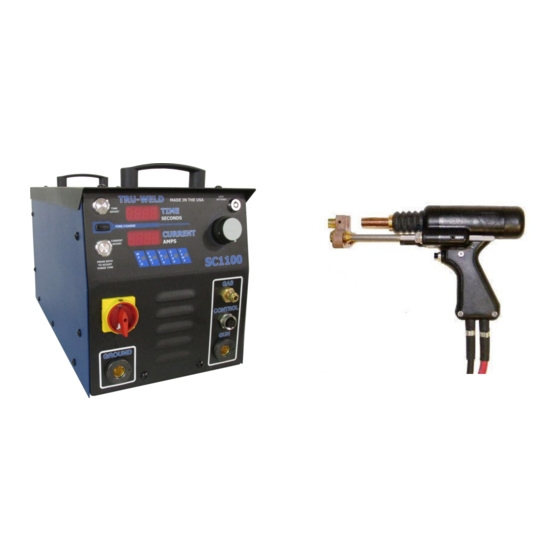
The SC1100 is a fully integrated stud welding system for ferrule-
shielded and gas-shielded drawn arc stud welding. The SC1100
contains digital controls for weld time, weld current, and gas purge
time. The system was designed to be a perfect fit for shop use, weld-
ing up through 5/8" studs. This is all contained in a compact, porta-
ble package.
TRU-WELD EQUIPMENT COMPANY
6400 N. Honeytown Road
Smithville, Ohio 44677
(330) 725-7744 Phone
(330) 669-2473 Fax
TWE@tfpcorp.com
http://truweldstudwelding.com
Stud Welding System
Version 2.1 03/24/2014
Advertisement
Table of Contents

Related Manuals for Tru-Weld TWE-SC1100


Summary of Contents for Tru-Weld TWE-SC1100
- Page 1 The system was designed to be a perfect fit for shop use, weld- ing up through 5/8” studs. This is all contained in a compact, porta- ble package. TRU-WELD EQUIPMENT COMPANY 6400 N. Honeytown Road Smithville, Ohio 44677 (330) 725-7744 Phone (330) 669-2473 Fax TWE@tfpcorp.com...
- Page 2 TRU-WELD EQUIPMENT LIMITED WARRANTY All goods produced by Truweld Equipment shall be warranted against defects including workmanship and components. No other war- ranties whether expressed, verbal, or implied will apply. Warranties only apply to the original equipment purchaser. Warranty claims will be limited to either repair or replacement of the defective materials by Truweld Equipment. At the option of Tru- weld Equipment the location of where the warranty evaluation and repairs are made will be determined.
- Page 3 Company and Product Information Company Profile Tru-Weld Stud Welding has been making weld studs since 1959, and since 1970 we have been pro- ducing our own line of high-quality stud welding equipment. Tru-Weld is located in Medina, Ohio and has product and equipment distributors across the nation. Tru-Weld Equipment Company (TWE) offers a full line of Drawn-Arc and Capacitor Discharge (CD) stud welding equipment, replacement parts, and accessories.
-
Page 4: Safety Symbols
Stud Welding Safety Precautions Safety is everyone’s responsibility. TRU-WELD designs every machine with safety in mind, and a safe work environment depends largely on you. Do not install, operate, or repair this equipment without carefully reading this manual and observ- ing all of the safety precautions mentioned. - Page 5 Stud Welding Safety Precautions ELECTRIC SHOCK Electric shock can injure or kill! Precautionary measures must be taken to provide maximum protection against electri- cal shock. Do not touch live or energized electrical parts or store metallic objects near power. ...
-
Page 6: Welding Sparks
Stud Welding Safety Precautions WELDING SPARKS Heat from flames and arcs can start fires. Hot slag or sparks can also cause fires and explosions. Remove all combustible materials from the work area or cover these materials with a protective non-flammable tarp. Combustible materials include wood, fabrics, sawdust, liquid and gas fuels, solvents, paints and coatings, paper, etc. - Page 7 SC1100 Product Specifications Weld Range 14ga to 5/8” Consistent welding regardless of stud diameter. Duty Cycle 14ga thru 1/4” Unlimited 3/8” 7-8 per minute 1/2” 4-5 per minute 5/8” 2-3 per minute Dimensions Height 12.6” (320mm) Width 11” (280mm) Length 22.4”...
-
Page 8: Electrical Input Requirement
SC1100 Setup and Installation Initial Steps Only qualified personnel should perform this installation. Turn the input power off at the disconnect switch or fuse box before working on the welder. Do not touch electrically hot parts. This section provides detailed instructions for the proper installation of the TWE SC1100. It is recommended that these instructions be followed carefully to allow for the best possible oper- ating environment. - Page 9 SC1100 Setup and Installation Preparing the Unit for Primary Power Only qualified personnel should perform this installation. Turn the input power off at the disconnect switch or fuse box before working on the welder. Do not touch electrically hot parts. Remove the top cover of the SC1100.
-
Page 10: Power / Ground Connections
SC1100 Setup and Installation Power / Ground Connections Electrical Input Requirement The SC1100 is equipped with an Input Voltage Jumper Block so you can operate the unit from different line voltages depending on your requirements. Simply plug in the appropriate voltage connector for either 230VAC (red wired connector) or 460VAC (black wired connector) 3 Phase operation. -
Page 11: Weld Cable Connection
SC1100 Setup and Installation Cable / Gas Connections Connection Weld Cable The SC1100 weld cable connection is located on the front of the welder Connect stud gun cable assembly directly to the SC1100. Plug stud gun control cable plug into the connector on the front of welder. Gas line connection When “gas shield”... - Page 12 Stud Gun Setup Stud Gun Setup Each stud welding application requires that the stud gun be set up properly for the correct stud and ferrule arrangement. Select the correct style and size of chuck for the stud to be welded and attach it to the stud gun.
- Page 13 Stud Gun Setup Lift Set the lift when all of the accessories and stud have been properly set on the stud gun, prior to welding. Plug the control connector of the stud gun directly into the stud welder (do not attach the weld cable).
- Page 14 Stud Gun Setup Free Travel Adjustment This adjustment can be used to control the force with which the stud is plunged into the molten weld pool by moving the engagement point of when the shaft of the stud gun engages the damp- ener.
- Page 15 Stud Gun Setup Attaching the stud gun to start welding Select the gun, control cable, and weld cable that is recommended for the specific type of welder and the job. Attach stud gun to weld and control cable extension. ...
- Page 16 SC1100 Operations - Settings SC1100 Power Switch/Power On The power switch for the SC1100 is located on the left front of the front control panel. Turn the red dial clockwise to the horizontal position ( I ) indicator to turn the unit ON. Turn the dial to the ver- tical position ( O ) indicator to turn the unit OFF.
- Page 17 SC1100 Operations - Settings Setting Welding Controls - Time and Current The time and current controls are located on the front of the welder. The controls consist of a Time Button, Current Button, Adjustment Dial, and a Fine/Coarse Switch. The digital display will indicate the settings chosen during setup.
- Page 18 SC1100 Operations - Settings SC1100 approximate time and current settings There is a chart of approximate settings for full-base diameter studs located on the top cover of the SC1100. Weld Counter and Weld Counter Reset The SC1100 is equipped with different counters to display the number of times the unit has drawn an arc or the stud gun has been actuated.
- Page 19 SC1100 Operations - Settings SC1100 Supervisor Lock The supervisor lock prevents the settings from being adjusted. The purpose is to allow a meas- ure of process control. All settings and the counter may be viewed when the lock is activated. To activate the lock, turn clockwise toward the 3 o’clock position.
- Page 20 Visually inspect weld. *** Note - when determining finished length required for the particular application, keep in mind the reduction in length (burn-off) from stud welding operations. TRU-WELD stud lengths are al- ways given before weld.
- Page 21 SC1100 Operations - Welding Stud Welding - Helpful Hints and Suggestions • Keep weld studs and ferrules clean and dry. • Set the time for the appropriate weld base diameter (see chart on page 18). • Set the amperage for the appropriate weld base diameter (see chart on page 18). •...
- Page 22 SC1100 Operations - Welding Visual Weld Inspection and Adjustments Good Weld After shooting the stud, break away ferrule and visually inspect the weld. The collar should be smooth and even around the entire stud. Partial Weld This is when the collar does not extend around the entire perimeter of the base of the stud.
- Page 23 SC1100 Troubleshooting Problem Possible Cause Unit will not turn on. No power. 1. Test 3 phase power. 2. Contact a TWE Rep. Fan does not run. Fan failure 1. Check fan for any obstructions. 2. Call your TWE Rep for repairs. Unit turns on, coil boot test is Bad connection or 1.
- Page 24 All tests should be performed by a qualified person. Always turn off power to the welder before working on or testing components within the welder. Contact your TRU-WELD Equipment Representative for replacement parts and for servicing your welding equipment.
- Page 25 TRU-WELD Equipment Company 6400 N. Honeytown Road Smithville, Ohio 44677 (330) 725-7744 Phone (330) 669-2473 Fax TWE@tfpcorp.com http://truweldstudwelding.com...
Need help?
Do you have a question about the TWE-SC1100 and is the answer not in the manual?
Questions and answers