
Related Manuals for Tru-Weld TW-i Series


Summary of Contents for Tru-Weld TW-i Series
- Page 1 OPERATOR’S MANUAL TW-i SERIES Capacitor Discharge Stud Welder MODELS: TW-i 250 TW-i 250CP TW-i 321 TW-i 375 TRU-WELD EQUIPMENT COMPANY www.truweldstudwelding.com (330) 725-7744...
-
Page 2: Table Of Contents
CONTENTS Description Pages Warranty Information Safety Specifications and Features Product Components Screen Operation Setup and Welding 9-11 CD Stud Gun Exploded View... -
Page 3: Warranty Information
Tru-Weld Equipment will be at the customer’s expense. At the option of Tru-Weld Equipment the defect will either be re- paired or replaced. Notice must be provided to Tru-Weld Equipment of a warranty defect within 30 days that the defect or failure is incurred. -
Page 4: Safety
SAFETY Read the safety notices before operating welder Electrical • Due to potential dangerous electrical input and output the equipment must be disconnected from all incoming power when servicing. Do not operate the equipment with the outer cover removed or with the case open. •... -
Page 5: Specifications And Features
SPECIFICATIONS AND FEATURES TW-i Capacitor Discharge Stud Welder Series The TW-i series of capacitor discharge stud welders incorporates the latest solid state technology into a compact, lightweight, and rugged CD stud welder. This full line of equipment is capable of welding pins, cup head pins, and CD studs ranging from 14-gauge up to 3/8”... -
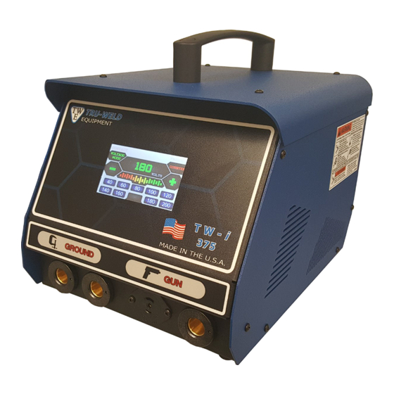
Page 6: Product Components
PRODUCT COMPONENTS Front View Back View Components 1. Touch Screen Interface 2. Weld Ground Connector 3. Cup Pin Weld Ground Connector (Model 250CP only, on all other TW-i models this connector is a secondary Weld Ground Connector) 4. Stud Gun Control Cable Connector 5. - Page 7 PRODUCT COMPONENTS Internal View Components 1. Ventilation Fan 2. ON/OFF Switch 3. 10A Fuse 4. AC Inline Filter/Power Cord Socket 5. Capacitor Bank 6. Freewheeling Diodes 7. SCR/Clamp 8. Discharge Resistor 9. Control Board...
-
Page 8: Screen Operation
SCREEN OPERATION Stud Preset Screen Contact Indicator Welding Voltage Trigger Indicator Stud Counter Mode Selection Voltage Adjustment Voltage Adjustment Charge Indicator Stud Presets Metric Stud Mode Voltage Preset Screen Mode Selection Voltage Presets... - Page 9 SCREEN OPERATION Stud Counter Screen Stud Count Stud Counter Reset Resetting the Stud Counter • While on the stud counter screen, press the RESET tab located at the bottom of the screen. • The screen will then prompt the user for a confirmation to clear the stud counter. •...
- Page 10 SCREEN OPERATION Screen Status Indicators Status Indicator Status Description Solution Indicator Unit needs to cool down before more welds can be Unit Has Exceeded OVERTEMP made. Please allow the unit to cool down and clear Temperature Threshold the overtemp warning. UNDER Insufficient Input Unit has detected insufficient supply power.
-
Page 11: Setup And Welding
SETUP AND WELDING Connecting the Welding Leads 1. Connect the stud gun weld cable into the gun terminal socket on the front of the welding unit. The cable end plug has a flat which aligns with a dot on the panel mount socket. Secure the connector into the panel mount socket, and then turn it clockwise until it locks into proper position. - Page 12 SETUP AND WELDING Selecting the Proper Stud Collet (Stud Holder) Listed below are the common collet styles, the choice between these setups is usually a matter of per- sonal preference 1. The B collet which is a two-piece assembly (collet and insert). The insert determines how much of the stud is engaged in the collet.
- Page 13 SETUP AND WELDING Powering On the Welder When all of the previous setup steps in this manual are complete the welder can be powered on. 1. Ensure that the power cord is connected to the power cord socket and the supply power. 2.
-
Page 14: Cd Stud Gun Exploded View
CD GUN EXPLODED VIEW... - Page 15 TRU-WELD Equipment Company 6400 N. Honeytown Road Smithville, Ohio 44677 (330) 725-7744 Phone (330) 669-2473 Fax TWE@tfpcorp.com http://truweldstudwelding.com Version 1.1 Date 5/25/2017...
Need help?
Do you have a question about the TW-i Series and is the answer not in the manual?
Questions and answers