Advertisement
Quick Links
Drawn Arc Gas Short Cycle
Operations Manual
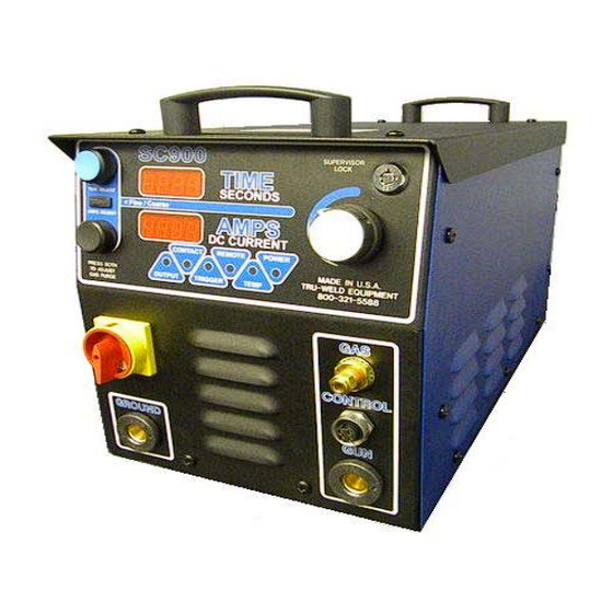
The SC900 is a fully integrated stud welding system for ferrule‐
shielded and gas‐shielded drawn arc stud welding. The SC900 con‐
tains digital controls for weld time, weld current, and gas purge time.
The system was designed to be a perfect fit for shop use, welding up
through 1/2" studs. This is all contained in a compact, portable pack‐
age.
TRU‐WELD EQUIPMENT COMPANY
6400 N. Honeytown Road
Smithville, Ohio 44677
(330) 725‐7744 Phone
(330) 669‐2473 Fax
TWE@tfpcorp.com
http://truweldstudwelding.com
TWE - SC900
Stud Welding System
Version 2.1 03/24/2014
Advertisement

Related Manuals for Tru-Weld TWE-SC900


Summary of Contents for Tru-Weld TWE-SC900
- Page 1 TWE - SC900 Drawn Arc Gas Short Cycle Stud Welding System Operations Manual The SC900 is a fully integrated stud welding system for ferrule‐ shielded and gas‐shielded drawn arc stud welding. The SC900 con‐ tains digital controls for weld time, weld current, and gas purge time. The system was designed to be a perfect fit for shop use, welding up through 1/2” studs. This is all contained in a compact, portable pack‐ age. TRU‐WELD EQUIPMENT COMPANY 6400 N. Honeytown Road Smithville, Ohio 44677 (330) 725‐7744 Phone (330) 669‐2473 Fax TWE@tfpcorp.com http://truweldstudwelding.com Version 2.1 03/24/2014 ...
- Page 2 TRU‐WELD EQUIPMENT LIMITED WARRANTY All goods produced by Truweld Equipment shall be warranted against defects including workmanship and components. No other war‐ ranties whether expressed, verbal, or implied will apply. Warranties only apply to the original equipment purchaser. Warranty claims will be limited to either repair or replacement of the defective materials by Truweld Equipment. At the option of Tru‐ weld Equipment the location of where the warranty evaluation and repairs are made will be determined. All warranty claim items re‐ turned to Truweld Equipment will be at the customer’s expense. At the option of Truweld Equipment the defect will either be repaired or replaced. Notice must be provided to Truweld Equipment of a warranty defect within 30 days that the defect or failure is incurred. Warranties are not transferable. This warranty does not apply for equipment which is used improperly in any fashion including but not exclusive to the following: Equipment which has been modified Equipment which has not been installed properly Equipment which has been used for purposes other than which it had been designed Equipment which has not been properly maintained Equipment which was continued to be used after a defect had been found Equipment which was damaged in any way Truweld Equipment will never be liable for consequential damages, loss, or expense occurring directly or indirectly from the use of the equipment covered in this warranty. All cables, cable sets and connectors are not warranted. Two (2) year warranty period from date of purchase TWE250 Power Supply SC1900 Power Supply TWE321 Power Supply SC1950 Power Supply TWE375 Power Supply SC2400 Power Supply SC900 Power Supply SC2402 Power Supply SC1400 Power Supply SC2420 Power Supply SC1450 Power Supply SC3400 Power Supply ...
- Page 3 Company and Product Information Company Profile Tru‐Weld Stud Welding has been making weld studs since 1959, and since 1970 we have been pro‐ ducing our own line of high‐quality stud welding equipment. Tru‐Weld is located in Medina, Ohio and has product and equipment distributors across the nation. Tru‐Weld Equipment Company (TWE) of‐ fers a full line of Drawn‐Arc and Capacitor Discharge (CD) stud welding equipment, replacement parts, and accessories. Our experienced Management and Staff is committed to provide the utmost in quality and service in every step of our production, while remaining competitive in the marketplace. It is our goal to meet our customer's needs more effectively than our competitors through a process of continuous quality improvement. Our long‐standing relationship with our customers' and suppliers' is our key to contin‐ ued success and growth. If we can be of any further assistance to you and your company, please do not hesitate to contact us. Product Information The SC900 is a fully integrated stud welding system for ferrule‐shielded and gas‐shielded drawn arc stud welding. The SC900 contains digital controls for weld time, weld current, and gas purge time. The system was designed to be a perfect fit for shop use, welding up through 1/2” studs. This is all con‐ tained in a compact, portable package. Features: ♦ Smooth arc curve targeted for small to medium sized diameter studs ♦ Enhanced Duty Cycle production requirements ♦ Capable of up to 100 feet of 2/0 welding cable accommodates a large variety of work station layouts ♦ Stepless time and current control allow for infinite settings for fine‐tuning the welding output ♦ Stud Job Counter that can be reset for every job ♦ On‐Demand Fan that cycles on and off when needed. Complete system Includes: 800 Amp Power Supply Controller, TWE19000 Light Duty stud gun, 25 feet of #1 AWG combo cable, and 15 feet of #1 AWG ground cable with clamp. 3 ...
-
Page 4: Safety Symbols
Stud Welding Safety Precautions Safety is everyone’s responsibility. TRU‐WELD designs every machine with safety in mind, and a safe work environment depends largely on you. Do not install, operate, or repair this equipment without carefully reading this manual and observ‐ ing all of the safety precautions mentioned. If there is a question, ask your supervisor! Safety Symbols Every effort has been made to protect trained operators from injury or unnecessary risk. Certain symbols are used throughout this manual to call attention to safety‐related information and in‐ struction. The safety symbols in this manual have these meanings: This symbol indicates Dangerous Situations. When this symbol is used in this manual, death or serious bodily harm is possible or probable if the corresponding preventative measures are not taken. Operators must take caution in the method and manner of handling or using the machine when this symbol is displayed. Safety Precautions Do not install, operate, or repair the SC900 welding equipment without reading this manual and all safety precautions stated within! This machine was designed and built with operator safety in mind, but safety begins with you! Every effort has been made to protect the trained operator from injury. Please become familiar with the information in this manual to minimize the risk of shock or injury. STUD WELDING CAN BE HAZARDOUS. ALWAYS PROTECT YOURSELF AND OTHERS FROM POSSIBLE INJURY OR DEATH. KEEP CHILDREN AWAY. Operators who have a pacemaker should consult with their physician before operating stud weld‐ ing equipment. FUMES and OXYGEN DEPLETION ♦ Only weld in areas or rooms where adequate ventilation of weld gases is possible and where there is not fire, smoke or explosion hazards. ♦ When working in a confined space always have trained support personnel nearby. ♦... - Page 5 Stud Welding Safety Precautions ELECTRIC SHOCK Electric shock can injure or kill! Precautionary measures must be taken to provide maximum protection against electri‐ cal shock. ♦ Do not touch live or energized electrical parts or store metallic objects near power. ♦ Ground the work or metal to be welded to a good electrical (earth) ground. ♦ Do not leave an energized machine unattended. ♦ Never work in wet clothing, gloves or footwear. ♦ Insulate yourself from work and ground using dry insulation. Make certain the insulation is large enough to cover your full area of physical contact with work and ground. ♦ Inspect all system components, protective equipment, cables, connectors and gas lines prior to operating equipment. Never use cables that are longer than necessary. ♦ When testing a live unit, use the one‐hand method. Do not put both hands inside of the unit. Keep one hand free. ♦ Disconnect input power conductors from de‐energized supply line before moving a welding power source. ♦ Always be sure the work cable makes a good electrical connection with the metal being welded. The connection should be as close as possible to the area being welded. ♦ Turn OFF welding power source before servicing unless the procedure specifically requires an energized unit. ♦ Never touch the energized stud or gun before discharging the stud to ground. ♦ Never use the power source to provide heat for thawing frozen pipes. ARC RAYS and EYE PROTECTION ...
- Page 6 Stud Welding Safety Precautions WELDING SPARKS Heat from flames and arcs can start fires. Hot slag or sparks can also cause fires and explosions. Remove all combustible materials from the work area or cover these materials with a protective non‐flammable tarp. Combustible materials include wood, fabrics, sawdust, liquid and gas fuels, solvents, paints and coatings, paper, etc. Hot sparks or hot metal can fall through cracks or crevices in floors or wall openings and cause a hidden smoldering fire. Make certain that such openings are protected from hot sparks and metal. ELECTRIC and MAGNETIC FIELDS Electric current flowing through any conductor causes localized Electro‐Magnetic Fields (EMF). Welding and cutting current creates EMF around welding cables and welding machines. ♦ Operators having pacemakers should consult their physician before welding. EMF may interfere with some type of pacemakers. ♦ Exposure to EMF may have other health effects, which are unknown. ♦ Operators should use the following procedures to minimize exposure to EMF: ♦ Route the work cables together. Secure them with electrical tape when possible. ♦ Never coil the work cable around any part of your body. ♦ Do not place your body between the work cables. Route cables on the same side of your body. ♦ Connect the work cable to the work piece as close as possible to the area being welded. ♦ Keep welding power source and cables as far away from your body as possible. ♦ Electromagnetic fields can irrevocable erase magnetic data carriers (computer memory, credit cards, security ID cards or data storage diskettes). ♦ Electromagnetic fields may magnetize and damage watches or similar digital devices. PROTECT YOURSELF and OTHERS! ...
- Page 7 SC900 Product Specifications Weld Range 14ga to 1/2” Consistent welding regardless of stud diameter. Duty Cycle 14ga thru 1/4” Unlimited 3/8” 5‐6 per minute 1/2” 2‐3 per minute Dimensions Height 12.6” (320mm) Width 11” (280mm) Length 22.4” (570mm) Weight 106 Lbs. (48kg) ...
-
Page 8: Handling And Unpacking The Welder
SC900 Setup and Installation Initial Steps Only qualified personnel should perform this installation. ♦ Turn the input power off at the disconnect switch or fuse box before working on the welder. ♦ Do not touch electrically hot parts. This section provides detailed instructions for the proper installation of the TWE SC900. It is recommended that these instructions be followed carefully to allow for the best possible operat‐ ing environment. Handling and Unpacking the Welder Immediately upon receipt of the welder, inspect the shipment for any damage and notify the carrier of such damage before accepting delivery. Then inspect welder for damage which may have occurred in transit. After removing the components from the shipping container(s), check the container for any loose parts. Remove all packing materials. Visually check all air passages of power source for any packing materials that may obstruct airflow through the welder. If the equipment is not being installed immediately, store it in a clean, dry, well‐ventilated area until in‐ stallation. Selecting a Location The location of the power source should be carefully selected to ensure satisfactory and depend‐ able service. Choose a location relatively close to a properly fused source of electrical power. Use care against toppling over if the machine is placed on a tilted surface or plane. It is important that the machine be located in an open area where air can circulate freely through the front and rear openings. If space is at a premium, leave at least 1 foot (300 mm) of clearance between the rear of the power source and wall or other obstruction. Electrical Input Requirement The welding power source is designed to be operated from three‐phase, 60Hertz, AC power sup‐ ply. Consult your local electrical utility if you have any questions on the electrical system at the present installation site. The SC900 should be operated from a separate, fused or circuit‐breaker protected circuit. 8 ... - Page 9 SC900 Setup and Installation Preparing the Unit for Primary Power Only qualified personnel should perform this installation. ♦ Turn the input power off at the disconnect switch or fuse box before working on the welder. ♦ Do not touch electrically hot parts. Remove the top cover of the SC900. All of the connections that will need to be made are accessi‐ ble with the top cover removed. Primary Power Cable Route the Primary Power Cable through the Power Inlet Hole in the center connector on the back‐ side of the welder. Connect the power leads (Black, White, Red) to the L1, L2, and L3 connectors as shown in photo Firmly tighten screws that hold the power leads in place. Attach the ground wire (Green) to the ground lug of as shown in above. Once the Primary Power Cable is connected, tighten Power Cable Clamp on the back of the welder, holding the power cable firmly in place. 9 ...
-
Page 10: Power / Ground Connections
SC900 Setup and Installation Power / Ground Connections Electrical Input Requirement The SC900 is equipped with an Input Voltage Jumper Block so you can operate the unit from dif‐ ferent line voltages depending on your requirements. Simply plug in the appropriate voltage con‐ nector for either 230VAC (red wired connector) or 460VAC (black wired connector) 3 Phase opera‐ tion. Ground Cable Connection The SC900 is equipped with one ground cable connection located on the front of the welder Secure the ground cable to welder and connect the ground clamp to the work surface the. 10 ... -
Page 11: Weld Cable Connection
SC900 Setup and Installation Cable / Gas Connections Connection Weld Cable The SC900 weld cable connection is located on the front of the welder Connect stud gun cable assembly directly to the SC900. Plug stud gun control cable plug into the connector on the front of welder. Gas line connection When “gas shield” welding connect the gas line from the foot piece of the stud gun into the gas fitting on the front of the SC900 by easy quick connect fitting. 11 ... - Page 12 Stud Gun Setup Stud Gun Setup Each stud welding application requires that the stud gun be set up properly for the correct stud and ferrule arrangement. ♦ Select the correct style and size of chuck for the stud to be welded and attach it to the stud gun. ♦ Select the proper length leg assemblies for the length of the stud. ♦ Select the proper foot piece best suited for your application. ♦ Select the grip to fit the ferrule which is provided with the stud to be welded. After all of the proper accessories have been mounted on the stud gun place the stud in the chuck and begin the alignment of the accessories. ♦ Make certain that a sufficient amount of the stud is inserted in the chuck so that the stud is held firmly. ♦ Attach the ferrule to the ferrule grip. ♦ Plunge setting; move the leg, foot and ferrule assembly so that the stud protrudes beyond the ferrule (1/8” for studs 1/2" and under in diameter 3/16” for studs up through 7/8” and 1/4” for 1” and 1‐1/4” diameter studs). ♦ Position this assembly so that the stud moves freely through the ferrule when you slide the shaft of the stud gun back and forth. 12 ...
- Page 13 Stud Gun Setup Lift Set the lift when all of the accessories and stud have been properly set on the stud gun, prior to welding. Plug the control connector of the stud gun directly into the stud welder (do not attach the weld cable). Turn on the stud welder and actuate the trigger of the stud gun with the stud and fer‐ rule in place. Note the retraction of the shaft of the stud gun. This is designated as the Lift. The lift setting should be about 3/32” for general welding applications and studs ranging in diameter through 3/4" this adjustment should be suitable. For larger diameter studs and select applications the lift should be adjusted to approximately 1/8”. Adjusting the lift: ♦ Remove the back cap of the stud gun. ♦ Loosen the two socket set screws around the periphery of the lift adjustment screw. ♦ To increase lift rotate the lift adjustment screw counter clockwise and to decrease lift rotate clockwise. ♦ With each turn check the lift by actuating the stud gun until the desired lift is achieved. ♦ Tighten the socket set screws to hold the lift adjustment screw in place to secure the selected setting. ♦ Replace the back cap of the stud gun. Set Screw Rear Coil Yoke Lift Adjusting Screw Gun Body 13 ...
- Page 14 Stud Gun Setup Free Travel Adjustment This adjustment can be used to control the force with which the stud is plunged into the molten weld pool by moving the engagement point of when the shaft of the stud gun engages the damp‐ ener. Rotating the dampener cover counter clockwise increases the amount of free travel. 14 ...
- Page 15 Stud Gun Setup Attaching the stud gun to start welding ♦ Select the gun, control cable, and weld cable that is recommended for the specific type of welder and the job. ♦ Attach stud gun to weld and control cable extension. ♦ Actuate the stud gun without placing it on the surface to be welded to assure that the con‐ nection through the control cable is correct to complete the circuit and actuate the stud gun. ♦ Make sure welder is set up properly to begin the welding process. ♦ Place the selected stud into the chuck and attach the ferrule to the ferrule grip. ♦ Place stud onto surface to be welded and press stud gun down until ferrule is flush with the welding surface. ♦ Trigger the gun and hold in place until cycle is completed. ♦ Pull gun assembly straight up off of the welded stud. ♦ Do not depress trigger when removing gun from stud. ♦ Remove the ferrule by breaking it off and inspect the weld. ♦ Make proper adjustments as needed. 15 ...
- Page 16 SC900 Operations ‐ Settings SC900 Power Switch/Power On The power switch for the SC900 is located on the left front of the front control panel. Turn the red dial clockwise to the horizontal position ( I ) indicator to turn the unit ON. Turn the dial to the ver‐ tical position ( O ) indicator to turn the unit OFF. When the welder is turned on, the digital display will go through a self‐diagnostic check. This takes approximately 3 to 5 seconds, and then the digital display will show the last time and current to which the unit was set. This denotes that the unit is ready to go. When connected to the welder, the stud gun will actuate 3 times, indicating that there is a good connection. SC900 Diagnostic Lights On the Control Panel, located below the digital display, is a row of diagnostic lights for the welder. OUTPUT ‐ When the stud gun is triggered, this light comes on to indicate that the OCV is present at the output terminals. TRIGGER ‐ When the stud gun is triggered, this light comes on to indicate that the trigger circuit is functioning properly, and that the welding unit is receiving feedback from the stud gun. POWER ‐ When this light is lit, it indicates that there is an error. TEMP ‐ When this light is lit, it indicates that either the main transformer or weld bridge has reached maximum temperature and that the unit will not function until it is cooled. REMOTE ‐ This function is not currently in use. 16 ...
- Page 17 SC900 Operations ‐ Settings Setting Welding Controls ‐ Time and Current The time and current controls are located on the front of the welder. The controls consist of a Time Button, Current Button, Adjustment Dial, and a Fine/Coarse Switch. The digital display will indicate the settings chosen during setup. When setting time or current, depress and hold down appropriate button, and turn Adjustment Dial clockwise or counter‐clockwise to the correct setting on the digital display. Use the Fine/Coarse Switch for setting the appropriate time or current ‐ this will toggle between 10’s or 100’s of amps and 10th’s and 100th’s of a second. To adjust gas purge time, hold both the TIME and AMPS buttons and turn Adjustment Dial. The setting is saved when the buttons are released. 17 ...
- Page 18 SC900 Operations ‐ Settings SC900 approximate time and current settings There is a chart of approximate settings for full‐base diameter studs located on the top cover of the SC900. Weld Counter and Weld Counter Reset The SC900 is equipped with different counters to display the number of times the unit has drawn an arc or the stud gun has been actuated. Perpetual Weld Counter (Non‐resettable) ‐ This is a running total of every time an arc is drawn on the machine. This is programmed from the factory and can not be reset. Perpetual Gun Counter (Non‐resettable) ‐ This is a running total of every time the stud gun is actuated whether an arc was drawn or not. Job Counter (Resettable) ‐ This is a running total of the number of welds since the counter was last reset. To view the job counter, set the Fine/Coarse Switch to the Fine position. Each weld will be recorded on the Current digital display. If the switch is in the Coarse position, the weld will still be counted, but will not be displayed. You can also view the Job Counter total by depressing the Adjustment Dial while the switch is in the Coarse position. To Reset the Job Counter; 1. Turn off unit. 2. Depress and hold down Time and Current buttons. 3. Turn on machine. 4. Keep holding down buttons until OUTPUT light flashes then release the buttons. 5. Job Counter will now be set at 0. 6. Weld count will now register on Current digital display. 18 ...
- Page 19 SC900 Operations ‐ Settings SC900 Supervisor Lock The supervisor lock prevents the settings from being adjusted. The purpose is to allow a meas‐ ure of process control. All settings and the counter may be viewed when the lock is activated. To activate the lock, turn clockwise toward the 3 o’clock position. To deactivate the lock, turn counter‐clockwise toward the 12 o’clock position. 19 ...
- Page 20 SC900 Operations ‐ Welding Stud Welding ‐ Step by Step The weld gun is positioned over the base material and the main gun spring is partially compressed. Hold gun perpendicular to work surface and hold ferrule firmly against the surface. The trigger is pressed and the stud lifts off the base, drawing an arc. The arc melts the end of the weld stud and the base material below. The arc shield (ferrule) concentrates the heat below the weld stud and contains the mol‐ ten metal within the weld zone. Do not move weld gun during weld. The main spring plunges the weld stud down into the molten pool of metal in the base material. The cycle is completed in less than a second and the resulting weld bond develops the full strength of the fastener in the weld zone. Allow metal to cool and withdraw gun from the stud, pulling the gun straight up off of the stud. The weld gun is withdrawn from the weld stud leaving and the ferrule. The ferrule is broken away and discarded. Visually inspect weld. *** Note ‐ when determining finished length required for the particular application, keep in mind the reduction in length (burn‐off) from stud welding operations. TRU‐WELD stud lengths are al‐ ways given before weld. Diameter of Stud Reduction in Length 1/4” thru 1/2” 1/8” ...
- Page 21 SC900 Operations ‐ Welding Stud Welding ‐ Helpful Hints and Suggestions • Keep weld studs and ferrules clean and dry. • Set the time for the appropriate weld base diameter (see chart on page 18). • Set the amperage for the appropriate weld base diameter (see chart on page 18). • Make sure the negative polarity is to the weld stud gun and ensure a good, clean ground con‐ nection. • Align accessories so they are centered and adjust legs so that 3/16” to 1/4” of the stud pro‐ trudes beyond the ferrule. • Make sure work surface is relatively clean so impurities do not affect weld. • Test the welds at the beginning of each shift or change in stud. • Check burn off (1/8” ), color (silver blue and shiny), and weld fillet (360 degree). • Visually inspect all welds. Thru‐Deck Stud Welding ‐ Helpful Hints and Suggestions • Keep weld studs and ferrules clean and dry. • Never attempt thru‐deck welding when the ambient temperature is below 32 • Deck must be layered flat on supporting members. •...
- Page 22 SC900 Operations ‐ Welding Visual Weld Inspection and Adjustments Good Weld After shooting the stud, break away ferrule and visually inspect the weld. The collar should be smooth and even around the entire stud. Partial Weld This is when the collar does not extend around the entire perimeter of the base of the stud. This normally occurs when the weld power is set too low. Irregular Weld This is when the collar forms a bumpy or jagged collar around the base of the weld stud. This normally occurs when the weld time is set too high. Porous Weld Collar This usually occurs from the oxidation of the weld pool resulting from the weld time being set too long and/or the current being too low. Reduce the current and/or reduce the weld time to correct. Weld Collar Off‐Center This is when the collar is heavy or thick on one half of the base of the weld stud. The stud may also be tilted. This usually results from movement from the gun during the weld process or the gun not being flush or perpendicular to the base material during welding. 22 ...
- Page 23 SC900 Troubleshooting Problem Possible Cause Fix Unit will not turn on. No power. 1. Test 3 phase power. 2. Contact a TWE Rep. Fan does not run. Fan failure 1. Check fan for any obstructions. 2. Call your TWE Rep for repairs. Unit turns on, coil boot test is Bad connection or 1. Test control cable by plugging weld tool directly into unit good, no trigger from weld faulty equipment. (4 conductor straight through wiring). gun. 2. Check gun trigger resistance (<100 ohms when closed). 3. Check to see if trigger LED on control panel responds. 4. Remove the top cover and the cover of the black box inside the machine. Locate Touch/Trigger Control Board #16002. Check and note the operation of the LED’s and report the status. Unit turns on, no coil test, no Bad connection or 1. Test control cable by plugging weld tool directly into unit lift from gun coil, trigger is faulty equipment. (4 conductor straight through wiring). ...
- Page 24 SC900 Troubleshooting Problem Possible Cause Fix Unit stops welding, Over heating. 1. Allow unit to cool until OverTemp LED turns off. OverTemp LED is on. 2. Slow down welding rate (fewer studs per minute). 3. Any fault in the OverTemp Thermostat Circuit will shut the system down. Weld output erratic or weak. Adjustments or set‐ 1. Check welding hand tool set up, lift, plunge, and acces‐ tings. sory adjustments. 2. Check ALL weld current carry leads and connections, in‐ cluding grounds. 3. Test the power loop by making welds on a test piece us‐ ing only the starter cable set. 4. Test 3 phase power to control contactor. 5. Check taps (if applicable) on main transformer. Weld gun lifts, but does not Gun maintenance. If this happens, it is most likely binding inside of the gun. Per‐ plunge. form routine gun maintenance or replace gun if needed. All tests should be performed by a qualified person. Always turn off power to the welder before working on or testing components within the welder. Contact your TRU‐WELD Equipment Representative for replacement parts and for servicing your welding equipment. ...
- Page 25 TRU-WELD Equipment Company 6400 N. Honeytown Road Smithville, Ohio 44677 (330) 725‐7744 Phone (330) 669‐2473 Fax TWE@tfpcorp.com http://truweldstudwelding.com 25 ...
Need help?
Do you have a question about the TWE-SC900 and is the answer not in the manual?
Questions and answers