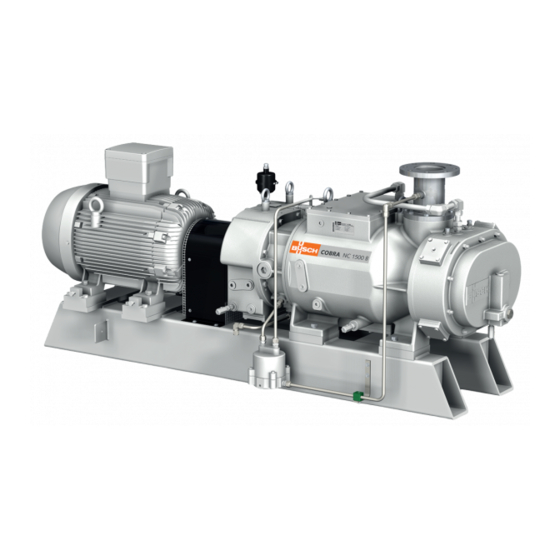
BUSCH COBRA NC 1500 B VR Instruction Manual
Dry screw vacuum pumps
Hide thumbs
Also See for COBRA NC 1500 B VR:

Subscribe to Our Youtube Channel
Related Manuals for BUSCH COBRA NC 1500 B VR


Summary of Contents for BUSCH COBRA NC 1500 B VR
- Page 1 Instruction Manual COBRA Dry Screw Vacuum Pumps NC 1500 B VR (Vapour Recovery) Ateliers Busch S.A. Zone industrielle, 2906 Chevenez Switzerland 0870573045/A0002_en / Original instructions / Modifications reserved 15/03/2019...
-
Page 2: Table Of Contents
Table of Contents Table of Contents 1 Safety........................... 4 2 Product Description ..................... 5 2.1 Operating Principle....................6 2.2 Application ......................6 2.3 Start Controls ....................... 6 2.4 Standard Features....................6 2.4.1 Cooling......................6 2.4.2 Sealing Systems ..................6 2.4.3 Liquid Return System .................6 2.5 Optional Accessories..................... - Page 3 Table of Contents 14 EU Declaration of Conformity ..................31 0870573045_NC1500B_VR_A0002_IM_en...
-
Page 4: Safety
Safety Prior to handling the machine, this instruction manual should be read and understood. If anything needs to be clarified, please contact your Busch representative. Read this manual carefully before use and keep for future reference. This instruction manual remains valid as long as the customer does not change anything on the product. -
Page 5: Product Description
Product Description | 2 Product Description Cooling liquid drain plug Cooling liquid inlet connection Cooling liquid outlet connection Eye bolt Earth connection (machine) Suction connection Injection point Level switch Magnetic plug Motor terminal box Nameplate Oil drain valve Oil fill plug Oil sight glass Discharge connection Liquid return system vessel... -
Page 6: Operating Principle
2 | Product Description 2.1 Operating Principle The machine works on the one-stage, twin-screw pump principle. Two screw rotors are rotating inside the cylinder. The pumped medium is trapped between the cylinder and screw chambers, compressed, and transported to the gas out- let. -
Page 7: Optional Accessories
Product Description | 2 2.5 Optional Accessories 2.5.1 Resistance Thermometer The resistance thermometer monitors the cooling liquid temperature. A second resistance thermometer might be installed to monitor the exhaust gas temperature. If a resistance thermometer is necessary to monitor the exhaust gas temperature, it may be installed in either the exhaust outlet flange of the pump or in a suitable prepared ex- haust spool piece at a distance of <... -
Page 8: Transport
3 | Transport Transport WARNING Suspended load. Risk of severe injury! • Do not walk, stand or work under suspended loads. NOTICE In case the machine is already filled with oil. Tilting a machine that is already filled with oil can cause large quantities of oil to in- gress into the cylinder. -
Page 9: Storage
• Make sure that the cooling liquid complies with the requirements, see Cooling Liquid Connection [► 11]. If the machine is installed at an altitude greater than 1000 meters above sea level: • Contact your Busch representative, the motor should be derated or the ambient temperature limited. 0870573045_NC1500B_VR_A0002_IM_en... -
Page 10: Connecting Lines / Pipes
– DN100 PN16, EN 1092-1 – ANSI 150, 4” (optional) If the machine is used as part of a vacuum system: • Busch recommends the installation of an isolation valve in order to prevent the machine from turning backwards. 10 / 32... -
Page 11: Discharge Connection
Installation | 5 5.2.2 Discharge Connection Connection size: At the machine discharge connection: – DN80 PN16, EN 1092-1 – ANSI 150, 3” (optional) • Make sure that the discharged gas will flow without obstruction. Do not shut off or throttle the discharge line or use it as a pressurised air source. •... -
Page 12: Filling Oil
Risk of premature failure! Loss of efficiency! • Only use an oil type which has previously been approved and recommended by Busch. For oil type and oil capacity see Technical Data [► 30] and Oil [► 30]. Oil filling at the motor side... - Page 13 Last oil change __ / __ / ____ Oil type see nameplate Change interval see instruction manual If there is no sticker (part no. 0565 568 959) on the machine: • Order it from your Busch representative. 0870573045_NC1500B_VR_A0002_IM_en 13 / 32...
-
Page 14: Fitting The Coupling
5 | Installation 5.5 Fitting the Coupling Coupling hub (motor side) Coupling hub (machine side) Elastic insert Ring Radial screw Max. admissible torque: 10 Nm Machine type Coupling size Value “E” (mm) ® NC 1500 B Samiflex A4CS In case of a machine delivery without motor: •... -
Page 15: Electrical Connection
• Provide an overload protection according to EN 60204-1 for the motor. • Make sure that the motor of the machine will not be affected by electric or electro- magnetic disturbance from the mains; if necessary seek advice from Busch. • Connect the protective earth conductor. -
Page 16: Wiring Diagram Three-Phase Motor (Pump Drive)
5 | Installation 5.6.1 Wiring Diagram Three-Phase Motor (Pump Drive) Delta connection (low voltage): Star connection (high voltage): NOTICE Incorrect direction of rotation. Risk of damage to the machine! • Operation in the wrong direction of rotation can destroy the machine in a short time! Prior to start-up, ensure that the machine is operated in the right direction. -
Page 17: Electrical Connection Of The Monitoring Devices
Installation | 5 5.7 Electrical Connection of the Monitoring Devices NOTE In order to prevent potential nuisance alarms, Busch allows that the control system is configured with a time delay of 2 seconds. NOTE The accessories below are considered as standard. -
Page 18: Operating Parameters
6 | Commissioning 5.8 Operating Parameters • Make sure that the cooling liquid and the injection liquid comply with the following requirements: Continuous cooling liquid injection rate* 3 … 6 l/min (INJ) Minimum constant cooling liquid injection 2 l/min rate (INJ) Cooling liquid flow rate (CLI) 18 l/min Ambiant temperature range (standard) -
Page 19: Start-Up
Commissioning | 6 CAUTION Noise of running machine. Risk of damage to hearing! If persons are present in the vicinity of a non noise insulated machine over extended periods: • Make sure that ear protection is being used. 6.1 Start-Up •... -
Page 20: Maintenance
Risk of injuries! Risk of premature failure and loss of efficiency! • Respect the maintenance intervals or ask your Busch representative for service. • Shut down the machine and lock against inadvertent start up. • Turn off the cooling liquid supply. -
Page 21: Maintenance Schedule
Monthly • Check the oil level, see Oil Level Inspection [► 22]. • Check the machine for oil leaks - in case of leaks have the machine repaired (contact Busch). Yearly • Carry out a visual inspection and clean the machine from dust and dirt. -
Page 22: Oil Level Inspection
7.3 Oil Change NOTICE Use of an inappropriate oil. Risk of premature failure! Loss of efficiency! • Only use an oil type which has previously been approved and recommended by Busch. Oil draining at the motor side 22 / 32 0870573045_NC1500B_VR_A0002_IM_en... - Page 23 Maintenance | 7 Cleaning cloth Magnetic plug Oil draining at the suction side Cleaning cloth Magnetic plug Drain pan 0870573045_NC1500B_VR_A0002_IM_en 23 / 32...
- Page 24 7 | Maintenance For oil type and oil capacity see Technical Data [► 30] and Oil [► 30]. Oil filling at the motor side Check oil level Oil filling at the suction side Check oil level When the oil filling is achieved: •...
-
Page 25: Checking The Liquid Return System
Oil type see nameplate Change interval see instruction manual If there is no sticker (part no. 0565 568 959) on the machine: • Order it from your Busch representative. 7.4 Checking the Liquid Return System Check the mechanism and clean it if necessary... -
Page 26: Overhaul
• Decontaminate the machine as much as possible and state the contamination status in a ‘Declaration of Contamination’. Busch will only accept machines that come with a completely filled in and legally binding signed ‘Declaration of Contamination’. (Form downloadable from www.buschvacuum.com) Decommissioning •... -
Page 27: Dismantling And Disposal
• The exclusive use of Busch genuine spare parts and consumables is recommended for the correct functioning of the machine and to validate the warranty. There is no standard spare parts kits available for this product, if you require Busch gen- uine parts: •... -
Page 28: Troubleshooting
Busch). Solid foreign matter has • Remove the solid foreign entered the machine. matter or repair the ma- chine (contact Busch). • Install an inlet filter if ne- cessary. The motor is defective. • Replace the motor. The machine does not reach Suction or discharge lines •... - Page 29 Oil Change [► 22]. The machine runs too hot. • See problem "The ma- chine runs too hot". For the solution of problems not mentioned in the troubleshooting chart contact your Busch representative. 0870573045_NC1500B_VR_A0002_IM_en 29 / 32...
-
Page 30: Technical Data
Oil capacity - motor side Oil capacity - suction side Weight approx. 1250 Please contact your Busch representative if the operating conditions fall outside of the recommended parameters as outlined. 13 Oil Shell Tellus S2 M Shell Tellus S2 V 68 TOTAL AZOLLA ZS... - Page 31 This Declaration of Conformity and the CE-mark affixed to the nameplate are valid for the machine within the Busch scope of delivery. This Declaration of Conformity is issued under the sole responsibility of the manufacturer. When this machine is integrated into a superordinate machinery the manufacturer of the superordinate machinery (this can be the operating company, too) must conduct the conformity assessment process for the superordinate machine or plant, issue the Declaration of Conformity for it and affix the CE-mark.
- Page 32 Colombia Korea South Africa www.buschvacuum.com/co www.buschvacuum.com/kr www.buschvacuum.com/za info@buschvacuum.co busch@busch.co.kr info@busch.co.za Czech Republic Malaysia Spain www.buschvacuum.com/cz www.busch.com.my www.buschvacuum.com/es info@buschvacuum.cz busch@busch.com.my contacto@buschiberica.es Denmark Mexico Sweden www.buschvacuum.com/dk www.buschvacuum.com/mx www.buschvacuum.com/se info@busch.dk info@busch.com.mx info@busch.se www.buschvacuum.com 0870573045/A0002_en / © Ateliers Busch S.A.
Need help?
Do you have a question about the COBRA NC 1500 B VR and is the answer not in the manual?
Questions and answers