
Subscribe to Our Youtube Channel
Related Manuals for nVent RAYCHEM TCONTROL-CONT-03


Summary of Contents for nVent RAYCHEM TCONTROL-CONT-03
- Page 1 TCONTROL-CONT-03 COMPACT MICROPROCESSOR CONTROLLER OPERATING AND INSTALLATION MANUAL...
-
Page 3: Table Of Contents
CONTENTS Section − 1 Introduction ............4 1.1 Preface ................ 4 1.2 Type designation ............5 1.3 Scope of delivery ............5 1.4 Accessories ..............5 1.5 Type-dependent factory settings ....... 6 Section − 2 Installation ............9 2.1 Installation site and ambient conditions ....9 2.2 Dimensions .............. -
Page 4: Introduction
Introduction Preface Please read this manual before commissioning the device. Keep the manual in a place accessible to all users at all times. Your comments are appreciated and may assist us in improving this manual. All necessary settings are described in this operating manual. Manipulations not described in the manual or expressly forbidden will jeopardize your warranty rights. Please contact the nearest subsidiary or the head office, should you encounter problems. The manual is valid from device software version 223.01.04 Chapter 4.7 “Display of the software version” Warning signs DANGER! This symbol indicates that Injury or death caused by electrical shock can/may occur, if the respective protective measures are not carried out. CAUTION! This symbol in combination with the signal word indicates that Damage to assets or data loss will occur, if the respective protective measures are not carried out. -
Page 5: Type Designation
Type designation Type key Type description 702071/9-1131-23-00 TCONTROL-CONT-03 (nVent Part No.: nominal dimension 48 mm x 48 mm 1244-0006829) • 1 analog input • 3 relays 702071/9-1134-23-00 TCONTROL-CONT-03/MA (nVent Part No.: nominal dimension 48 mm x 48 mm 1244-0006830) • 1 analog input • 2 relays • 1 analog output (user configurable 0/4…20 mA or 0/2…10 V) 702071/9-1131-23-53 TCONTROL-CONT-03/COM (nVent Part No.:... -
Page 6: Type-Dependent Factory Settings
The following tables show the type-dependent factory settings. The standard factory settings are shown in the respective sections of this manual. The settings for type TCONTROL-CONT-03 are also valid for type TCONTROL-CONT-03/COM. The settings for type TCONTROL-CONT-03/MA are also valid for type TCONTROL-CONT-03/COMA. - Page 7 Configuration level (ConF) cont... Parameter Factory setting for type TCONTROL- CONT-03 TCONTROL- CONT-03/MA Limit comparator 1 (LC1): Function (FnCt) Alarm value (AL) Response by Out of 1 (= ON) 1 (= ON) Range (ACrA) Limit comparator 2 (LC2): Function (FnCt) Alarm value (AL) 120.0 120.0 Response by Out of 1 (= ON) 1 (= ON) Range (ACrA) Binary outputs (OutL):...
- Page 8 User level (USEr) configuration Factory setting for type TCONTROL-CONT-03 TCONTROL-CONT-03/MA Parameter Name Parameter Name Set point 1 Set point 1 Limit comparator 1: Limit comparator 1: Limit Limit value value (Alarm value) (Alarm value) Limit comparator 2: Limit comparator 2: Limit Limit value value...
-
Page 9: Installation
Installation Installation site and ambient conditions The ambient conditions at the installation site must meet the requirements specified in the technical data. Chapter 8.1 “Technical Data” The device is not suitable for use in areas with an explosion hazard (Ex areas). Cleaning the device front The device front can be cleaned using warm or hot water (possibly adding slightly acidic, neutral or slightly alkaline cleaning agent). It has a limited resistance to organic solvents (e. g. methylated spirits, white spirit, etc.). Do not use abrasive or high-pressure cleaning equipment. Dimensions Close mounting Minimum spacing of panel cut-outs horizontal vertical without setup plug > 8 mm >... -
Page 10: Electrical Connection
Electrical connection Installation notes • The choice of cable, the installation and the electrical connection of the device must conform to the requirements of VDE 0100 “Regulations on the Installation of Power Circuits with Nominal Voltages below 1000 V” or the appropriate local regulations. • The electrical connection must only be carried out by qualified personnel. • The instrument shall be operated by mains protected with a branch circuitry overcurrent protection device not more than 20 Amps. For servicing/repairing a Disconnecting Device shall be provided to disconnect all conductors. • The load circuit must be fused for the maximum relay current, in order to prevent the output relay contacts becoming welded in the event of a short circuit occurring at that point. • The electromagnetic compatibility conforms to the standards and regulations cited in the technical data. •... -
Page 11: Electrical Isolation
Electrical isolation 2300 V AC 30 V AC (1) Analog input 50 V DC (2) Binary inputs/Output K3 (Logics) (3) Setup interface 30 V AC 50 V DC (4) Voltage supply (5) RS485 interface (6) Analog output 2300 V AC (7) Outputs K1, K2 and K4 (relay) Connection diagram 0/4—20mA 0/2—10V (5.1) (5.2) 0/14V 0/2—10V (6.1) 0/4—20mA N(L-) (6.2) (6.3) (6.4) -
Page 12: Operation
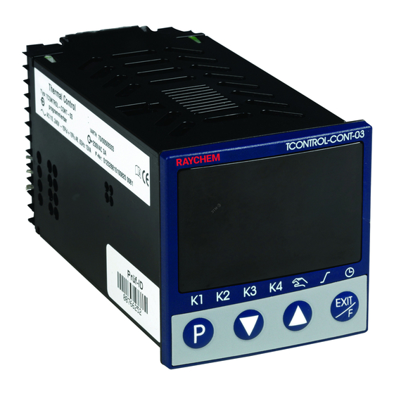
Operation Display and operating elements (1) Red 7-segment display (factory-setting: Process value); 4-digit, configurable decimal place (automatic adjustment on display overflow) (2) Green 7-segment display (factory-setting: Set point value); 4-digit, configurable decimal place, serves also for operator guide (display of parameter and level symbols) (3) Signals, yellow LED Switching states of the binary outputs 1 ... 4 (display lit = ON) (4) Keys Programming key l eave level/function key Chapter 7.8 “Display/Operation/Service counter” Value reduction/previous parameter Value increase/next parameter (5) Signals, green LED • Manual mode active • Ramp function active •... -
Page 13: User Level Configuration
A maximum of eight frequently used parameters can be made available in the User level. Use the Setup program to configure these parameters. O nce these parameters are selected a customer friendly name can be assigned. Names can consist out of maximum four characters (represented on 7-segment display). If no name is assigned the factory defaults will be used. Figure shows the menu of the Setup program (in case of TCONTROL-CONT-03/MA and .../COMA parameter 8 is switched off) nVent.com | 13... -
Page 14: Defining Various User Levels
Defining various user levels Access to the individual levels can be inhibited. Operator, User Parameter Configuration Code level level level free free free free free inhibited free inhibited inhibited inhibited inhibited inhibited 1. For code entry use (simultaneously for > 5 s) 2. Change code by pressing (display blinks!) 3. Enter code using (Ex-factory: all levels enabled) 4. Return to the normal display using or automatic return after 180 s T he parameter and configuration level can also be inhibited via the binary function. -
Page 15: Controller
Time entry A decimal place is mapped in the centre and on the right to display times. The time unit can be configured. Chapter 7.5 “Timer” Change value Select Parameter (bottom - green) (top - red) Parameter flashes 1. Select parameter by pressing 2. Change to the entry mode using (lower display blinks) 3. -
Page 16: Display Of The Software Version
Changing to the manual mode I n the manual mode, the controller output value can be changed manually. 1. Change to the manual mode using function key (> 2 s) (ex-factory setting) The output value is displayed in percent in the lower display. The "Manual mode active" LED is also lit. 2. Change the output value using With a modulating controller, the actuator is opened or closed using the keys. The various levels can be accessed in the manual mode. T he Setup program can be used to configure the default output value on a changeover. The manual mode can also be inhibited. Chapter 7.2 “Controller” T he controller automatically changes to manual mode in the event of overrange/underrange and probe break. Manual mode exit 1. Exit the manual mode using function key (> 2 s) Operation via binary functions F urther operating possibilities for the fixed value controller can be realised via binary functions. -
Page 17: Operator Level
Operator level Parameters Depending on the configuration, the following values are displayed: Symbol Meaning Set point value 1 (can be edited) SP 1 Set point value 2 (can be edited), only when switching SP 2 over to set point value 2 v Chapter 7.7 “Binary functions” Ramp set point value (only if configured) Chapter 7.3 “Ramp function” inP 1 Measured value of analog input 1 Output value Timer time (only if configured and timer is not running) Chapter 7.5 “Timer” Timer running time (only if timer runs) Chapter 7.5 “Timer” Residual timer running time (only if timer runs) Chapter 7.5 “Timer” Service counter display (only if service counter runs or as long as a reached limit value was not reset) Chapter 7.8 “Display/Operation/Service counter” Parameter level Normal display OPr/USEr PArA Parameter level PArA >2s... - Page 18 Value Parameters Symbol range Description Proportional 0…9999 Proportional band band At Pb1,2 = 0, the controller structure 0…9999 is ineffective. For the continuous controller Pb1,2 must be > 0. Derivative 0… Influences the differential component time 9999s of the controller output signal The larger the derivative time the higher the effectiveness of the D component. Reset time 0… Influences the integral component of 9999s the controller output signal The larger the reset time the lower the effectiveness of the I component.
-
Page 19: Configuration Level
Standard factory settings are shown bold. Non-standard factory settings: Chapter 1.5 “Type-dependent factory settings” Parameter display independent of the controller type: Chapter 7.2 “Controller” Decimal places for some parameters depend on the device setting: Chapter 7.8 “Display/Operation/Service counter” Configuration level Normal display OPr /USEr PArA Configuration level ConF ConF... - Page 20 Analog selector Some parameters in the Configuration level allow users to select from a series of analog values. The list below shows all available options. Value Description Deactivated Analog input Process value Current set point value Ramp limit value Ramp set point value (Reserved) (Reserved) Set point value 1 Set point value 2 Controller output value (-100%…+100%) Controller output 1 (0…+100%; e. g. “Heating”) Controller output 2 (0…-100%; e. g. “Cooling”) Timer run time (time unit of the timer) Residual timer run time (time unit of the timer) (Reserved) (Reserved) (Reserved) 20 | nVent.com...
-
Page 21: Analog Input
Analog input One analog input is available. ConF -> i nP -> Parameters Value / Selection Description Sensor type Pt100, 3 wire SEnS Pt1000, 3 wire Pt100, 2 wire Pt1000, 2 wire KTY 2 wire (reserved) Cu-CuNi T Fe-CuNi J Cu-CuNi U Fe-CuNi L NiCr-Ni K Pt10Rh-Pt S Pt13Rh-Pt R Pt30Rh-Pt6Rh B NiCrSi-NiSi N NiCr-CuNi E W5Re_W26Re C W3Re_W25Re D W3Re_W26Re 0…... - Page 22 Value / Parameters Selection Description -1999 … The measured value correction (offset) Measured value offset 0 … +9999 is used to correct a measured value by a certain amount upward or downward. OFFS Examples: Measured value Offset Displayed value 294.7 +0.3 295.0 295.3 -0.3 295.0 -1999 … Scale low On transducers with standard signal, a level +9999 display value is assigned to the physical signal (scaling). Example: 0 … 20 mA = 0 … 1500°C. -1999 … Scale high The range of the physical signal can be level +9999...
-
Page 23: Controller
Controller C ontroller type and controller input values, set point limit values, functions for manual mode and the presettings of self- optimization are set here. ConF -> Cntr -> Value / Parameters Selection Description Controller type 2-state controller 3-state controller CtyP Modulating controller Continuous controller Control Direct direction Inverse CACt (1) = Inverse: Output value Y of the controller is > 0, if process value x is smaller than set point value w (e.g. heating). (2) = Direct: Output value Y of the controller is > 0, if process value x is higher than set point value w (e.g. cooling). -
Page 24: Ramp Function
Value / Parameters Selection Description Set point -1999 … The set point limitation prevents the entry limit low +9999 of values outside the default range. The set point limit values are not effective when entering set point default values Set point -1999 … via the interface. The correction value limit high +9999 is limited for external set point values with offset. (analog Determines the source of the controller Process value for controller selector) process value. Analog Page 16, Analog selector input... - Page 25 ConF -> rAFC -> Value / Parameters Selection Description deactivated Function Ramp Kelvin/Minute FnCt Ramp Kelvin/Hour Ramp Kelvin/Day The ramp limit value can be changed using keys. t2 t3 (1) = Set point value (2) = Process value t1: Power ON/Ramp start (w1 active) t2-t3: Mains failure/Manual mode/Probe break t4-t5: Ramp stop t6: Set point value changeover to w2 The ramp function can be stopped, cancelled and restarted using binary functions. Chapter 7.7 “Binary functions” Ramp rate 0.0… Value of ramp rate 999.9 (for functions 1 to 3 only) rASL 0…9999...
-
Page 26: Limit Comparators
TIP! T he ramp function is cancelled in the event of a probe break or in manual mode. The outputs react in the same manner as for an overrange/underrange (configurable). Limit comparators L imit comparators can be used to monitor the process value against defined alarm limits. The way the limit comparators operate can be configured by the user (lk1 to lk8). Once an alarm limit (alarm set point) is exceeded, an alarm signal can be ouput or an internal function can be initiated. T here are 2 limit comparators available (LC1, LC2). The switching differential HySt can be user defined and will always be symmetrical in relation to the alarm set point (AL). Alarm value AL relative to the set point value w The limit comparator functions lk1 to lk6 monitor the process value x for an alarm value AL which is relative to the set point value w. This means that if the set point is changed the absolute... - Page 27 Fixed alarm value AL The limit comparator functions lk7 and lk8 monitor the process value x for a fixed alarm value AL to be set. HySt HySt ConF -> LC -> LC1, LC2 -> Value / Parameters Selection Description no function Function FnCt Function -1999 … Alarm value (limit value) to be monitored (see limit comparator functions lk1...lk8: +9999 alarm value AL) Alarm value range for lk1 and lk2: 0 ... 9999 0… Hysteresis in respect to the alarm value Hysteresis 1 … (see limit comparator functions lk1...lk8: HySt 9999 hysteresis HySt) Switching state in the event of overrange Response by Out of Range...
-
Page 28: Timer
Timer Timer signal A timer signal (tF1) is provided which can be transmitted via binary outputs or used for internal links, e. g. to switch off the controller (output value 0%) or to toggle the set point values. Chapter 7.6 “Outputs“ and Chapter 7.7 “Binary functions” The timer signal is active either when the timer runs or during the timer follow-up time (see below). The signal can be inverted via the “SiGn” parameter. Timer time The timer runs for the set time t1. Timer time, current timer running time and residual timer time can be displayed in the operator or User level (the timer time can also be changed here). - Page 29 Timer signal for t2 = 0 for t2 = 1...9999 (or -1) “Timer running” “Timer waiting” “Timer completed” for t2 = 0 for t2 = 1...9999 (or -1) Waiting time Timer time t1 + Waiting time Timer follow-up time t2 1 Timer started 4 Timer elapsed 2 Timer stopped...
-
Page 30: Outputs
Value / Parameters Selection Description Set time t2 -1… This time (in seconds) can be used to 0… transmit a time limited or acknowledgeable (Timer follow- +9999 signal after the timer time has elapsed. up time) 0 = switched off 1…9999 = active for the set time -1 = active until acknowledged Acknowledgement: For t2 = -1 the timer follow-up time is infinite. Cancel the signal using a function... - Page 31 ConF -> OutP-> OutL -> Value / Parameters Selection Description No function Binary outputs Controller output 1 0ut1 (e.g.“Heating”, with inverse control direction) 0ut2 Controller output 2 (e.g. “Cooling”, see above) 0ut3 Binary input 0ut4 (reserved) Limit comparator 1 Limit comparator 2 Timer signal Timer runs Timer completed Timer waiting (reserved) (reserved) Tolerance band signal, ramp Ramp end signal Service alarm (reserved) Actuate the F key...
-
Page 32: Binary Functions
Value / Parameters Selection Description -1999 … A value range of the output variable is Zero point 0… assigned to a physical output signal. 0Pnt +9999 The ex-factory setting corresponds to an output value of 0 ... 100 % for controller -1999 … End value outputs. 100… No changes of the ex-factory setting are +9999 required for continuous controllers. For a 3-state controller, enter the following settings for cooling: Zero point = 0 / End value = -100 Example (function as a transducer): The analog output (0...20 mA) is to be used to put out the process value (value range: 150...500 °C), this means: 150…500°C = 0…20 mA Zero point: 150 / End value: 500 Binary functions... - Page 33 Further functions via Setup program In the Setup program binary functions can be combined with each other (selection under “Additional functions”). It is also possible to select “Text display” as an additional function. A maximum of 4 characters can be entered as text (“Text display” button) and displayed with a 7-segment display. The text appears in the lower display when the binary function is active. ConF -> b nF Value / Parameters Selection Description Binary inputs no function Start self-optimization b n 1 Abort self-optimization b n2 Change to manual mode Controller off (controller outputs are Limit switched off) comparators Switch on controller Inhibit manual mode Stop ramp...
-
Page 34: Display/Operation/Service Counter
Display/Operation/Service counter Both displays can be adapted to the respective requirements by the configuration of the displayed value, the decimal place and the automatic change (timer). The time-out of the operation, the function key assignment and the level inhibit can also be configured. ConF -> d SP -> Value / Parameters Selection Description (Analog Display value for the upper display Upper display selector) d SU Process value Lower display (analog Display value for the lower display selector) d SL Current set point value Time appears in the lower display Display change to timer value (only effective after the timer is started) - Page 35 Value / Parameters Selection Description Function key Function if the key is briefly pressed in the short normal display (max. two seconds) no function (Push time Starting the timer < 2 seconds) Timer abort Stop timer/continue timer run Timer start/abort Display timer value (manual) Function key Function if the key is pressed for more than long two seconds in the normal display tASt Change to manual mode (Push time Starting the timer >2 seconds)
- Page 36 Value / Parameters Selection Description Service interval Number: Limit value for service counter (when select. “Number” in increm. of 1000) (Setup) 0… 0 = Service counter switched off 9999000 oCAL The service counter can be used to monitor Time (h): a binary signal in respect to number 0…999 (switch-on edge) or time (ON state). Time (d): 0…999 The service counter is started when entering a value > 0. When the limit value is exceeded, a signal is generated which can be put out to a binary output. The signal can only be acknowledged by resetting the limit value to zero (service counter switched off).
- Page 37 Controller Selection of the binary signal to be monitored Signal to be monitored output 1 Setting in the Setup program (-> Display/ (Setup) Operation/Service counter -> Service counter): - deactivated - Controller output 1 - Controller output 2 - Binary input 1 - Binary input 2 - Limit comparator 1 - Limit comparator 2 - Timer signal - Timer runs - Timer completed - Timer waiting - Tolerance band signal - Ramp end...
-
Page 38: Interface
Interface The device can be integrated into a data network (Modbus) via an optional RS485 interface. ConF -> i ntF -> Value / Parameters Selection Description 9600 bps Baud rate 19200 bps bdrt 38400 bps 8 data bits, 1 stop bit, no parity Data format 8 data bits, 1 stop bit, odd parity 8 data bits, 1 stop bit, even parity 8 data bits, 2 stop bits, no parity 0…1… Address in data network Device address 0 …... -
Page 39: Supplement
Supplement Technical Data Thermocouple input Designation Ambient Measuring Measuring temperature range accuracy coefficient Fe-CuNi “L” -200… +900 °C ≤ 0.25% 100 ppm/ K Fe-CuNi “J” 60584 -200…+1200 °C ≤ 0.25% 100 ppm/ K Cu-CuNi “U” -200… +600 °C ≤ 0.25% 100 ppm/ K Cu-CuNi “T” 60584 -200… +400 °C ≤ 0.25% 100 ppm/ K NiCr-Ni “K” 60584 -200…+1372 °C ≤ 0.25% 100 ppm/ K NiCr-CuNi “E” 60584 -200… +900 °C ≤ 0.25% 100 ppm/ K NiCrSi-NiSi “N”... - Page 40 RTD temperature probe input Designation, Measuring Measuring Ambient temperature Connection type range accuracy coefficient Pt100 EN -200… +850 °C 50 ppm/K 60751 2 wire connection 3 wire ≤ 0.4% connection ≤ 0.1% Pt1000 EN -200…+850 °C 50 ppm/ K 60751 2 wire connection 3 wire ≤ 0.2% connection ≤ 0.1% KTY11-6 -50…+150 °C 50 ppm/ K...
- Page 41 Binary inputs Potential-free contact open = inactive closed = active Measuring circuit monitoring In the event of a fault, the outputs change to defined statuses (configurable). Input sensor/ Overrange/ lead short- Input sensor/ Sensor underrange circuit lead break Thermocouple • – • Resistance • • • thermometer Voltage • • • 2—10 V (•) –...
- Page 42 Controller Controller type 2-state, 3-state, modulating controller, continuous controller Controller P/PI/PD/PID structures A/D converter 16 bit resolution Sampling cycle 250 ms time Timer Accuracy ±0.8 % ± 25 ppm/K Electrical data Supply voltage AC 110—240 V -15/+10%, 48—63 Hz (switch mode PSU) AC/DC 20—30 V, 48 — 63 Hz Electrical safety acc. to EN 61010, part 1 Overvoltage category III, pollution degree 2 Amperage max. 15 VA Data backup EEPROM Electrical at the back via screw terminals, connection Conductor cross section up to max. 1.3 mm Installation information on conductor cross sections Solid core ≤ 1.3 mm...
-
Page 43: Alarm And Fault Messages
Operating position Protection type acc.to EN 60529, at the front IP 65, at the rear IP 20 Weight approx. 123 g (fully equipped) Interface Interface type RS485 Protocol Modbus Baud rate 9600, 19200, 38400 Device address 0—255 Max. number of stations Alarm and fault messages Thermocouple input Fault remedy Display Cause Test/repair/replace Binary function for Carry out the measure ALrt (factory-specific which a text display intended for this case text, can be was configured is changed) -
Page 44: Self-Optimization
Self-optimization Principle Self-optimization (SO) is carried out according to the oscillation method and establishes the optimum controller parameters for PID or PI controllers. Depending on the configured controller type, the following controller parameters are defined: Proportional band (Pb), derivative time (dt), reset time (rt), cycle times (Cy), filter time constant (dF) Depending on the range of the control deviation, the controller selects between to methods a or b: a) SO in start-up phase b) SO at set point S = Switching level T = Start of self-optimization (SO) Prerequisites The following prerequisites must be fulfilled to be able to start self- optimization:... - Page 45 • For continuous controller only: Ensure that the function of the output (OutP -> OutA) is configured to controller output 1 and scaled to 0...100%. This means: Function (FnCt) = Controller output 1 (11) Zero point (0Pnt) = 0 End value (End) = 100 • For modulating controllers only: Determine the actuator time (tt) and set in the Parameter level Start of self-optimization 1. Simultaneously press the + keys (> 2 s) In the lower display, “tUnE” appears flashing. Self-optimization is completed when the display automatically changes to the standard display. The duration of self-optimization depends on the process. Canceling self-optimization 1.
- Page 46 46 | nVent.com...
- Page 47 nVent.com | 47...
- Page 48 België / Belgique Italia Россия Tel. +32 16 21 35 02 Tel. +39 02 577 61 51 Тел. +7 495 926 18 85 Fax +32 16 21 36 04 Fax +39 02 577 61 55 28 Факс +97 495 926 18 86 salesbelux@nvent.com salesit@nvent.com salesru@nvent.com Bulgaria Lietuva/Latvija/Eesti Serbia and Montenegro Tel. +359 5686 6886 Tel. +370 5 2136633 Tel. +381 230 401 770 Fax +359 5686 6886 Fax +370 5 2330084 Fax +381 230 401 770 salesee@nvent.com info.baltic@nvent.com salesee@nvent.com Česká Republika Magyarország Schweiz / Suisse Tel. +420 602 232 969 Tel. +36 1 253 7617 Tel. +41 (41) 766 30 80 czechinfo@nvent.com Fax +36 1 253 7618 Fax +41 (41) 766 30 81 saleshu@nvent.com infoBaar@nvent.com Denmark...
Need help?
Do you have a question about the TCONTROL-CONT-03 and is the answer not in the manual?
Questions and answers