
Subscribe to Our Youtube Channel
Related Manuals for nVent RAYCHEM 465


Summary of Contents for nVent RAYCHEM 465
- Page 1 465 Controller for Fire Sprinkler Trace Heating Systems INSTALLATION, OPERATION AND MAINTENANCE MANUAL...
-
Page 2: Table Of Contents
2.5.2 Temperature Sensor and Extension Cables ..... 11 2.6 Supervisory Relay Connections ............. 12 2.7 Initializing the Controller ................. 13 2.7.1 Initial Heating Cable Test .......... 13 465 Controller Operation ..............14 3.1 Quickstart ....................14 3.2 Settings Menu ..................16 3.3 System Menu..................16 3.3.1 Info ................ - Page 3 3.5 General Settings Menu ................22 3.5.1 Language ..............22 3.5.2 Country ..............22 3.5.3 Date ................22 3.5.4 Time ................22 3.5.5. Voltage ..............22 3.5.6 Select Unit of Measure ..........22 3.5.7 Time Format .............. 22 3.6 Supervisory Events ................23 3.6.1 Filter Times ..............
-
Page 4: Overview
Additional copies of this user manual may be ordered separately through your nVent Thermal Management representative or online at nVent.com. This document covers the 465 controller and its available options. This fire sprinkler heat trace controller is designed for the following trace heating products necessary to make up... -
Page 5: Product Overview Description
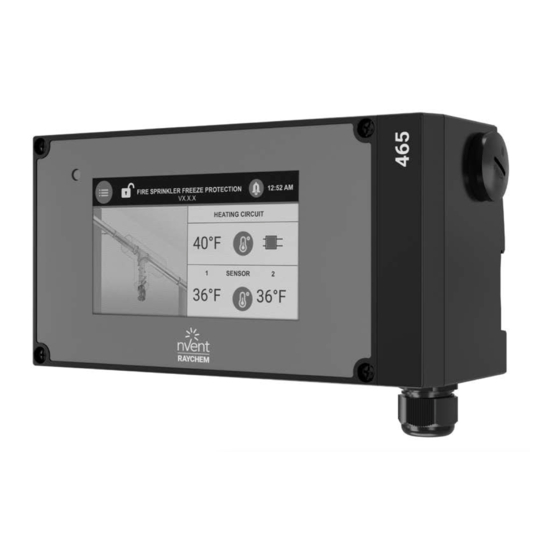
The 465 controller monitors, controls, and communicates supervisory events and data for one heating cable circuit. The intended use of 465 controller is to control and monitor heat tracing circuits for fire sprinkler systems. Each unit is a single point controller with a 5" inch color touch screen display for intuitive set up and programming right out of the box. - Page 6 High Temperature Cutout High temperature cutout is provided for both temperature sensor inputs. Low Current Condition The 465 controller offers a low current condition to identify situations where the heating cable is not pulling adequate current. Electromechanical Relay (EMR) Output The 465 controller is equipped with a 24A rated electromechanical relay (EMR) output switch with device failure supervisory status change.
-
Page 7: Product Ratings
to radio or television reception, which can be determined by turning the equipment off and on, the user is encouraged to try to correct the interference by one or more of the following measures: • Reorient or relocate the receiving antenna. •... - Page 8 Current Low condition 0.25 A Temperature Sensor Inputs Quantity Two inputs standard Types Thermistor 2KΩ/77°F (25°C), 2 Wire 10 ft (3 m) long, can be extended to 328 ft (100 m ) / 2 x 16 AWG Sensor temperature range -40°F (-40°C) to 194°F (90°C) Sensor data Temperature (°F)
- Page 9 Enclosure Mounting DIN Rail 35 mm (Indoor only) *Note: The 465 controller can't monitor the load current and ground fault current in each cable segment when an external contactor is used. These supervisory conditions are disabled when external contactor is used.
-
Page 10: Installation And Wiring
This section includes information regarding the initial inspection, preparation for use, and storage instructions for the 465 controller. Note: If the 465 controller is used in a manner not specified by nVent Thermal Management, the protection provided by the controller may be impaired. -
Page 11: Wiring
Grounding hubs and conductors must be installed in accordance with Article 250 of the National Electrical Code and Part I of the Canadian Electrical Code. 2.5.1 Power and Load Connections The 465 controller may be powered directly from a 120 V to 277 V supply. nVent.com/RAYCHEM | 10... -
Page 12: Temperature Sensor And Extension Cables
Figure 2.3 – Heating Cable Connection 2.5.2 Temperature Sensor and Extension Cables The 465 controller has two (2) temperature sensor inputs. Use only 2-wire Thermistor 2 KOhm / 77°F (25°C) sensors provided. Sensor 1 should be connected to terminals S1 ┴... -
Page 13: Supervisory Relay Connections
Figure 2.4 – Temperature Sensor Wiring 2.6 SUPERVISORY RELAY CONNECTIONS The 465 controller includes terminals for one supervisory relay as shown in figure 2.5. It can support both AC and DC power source (please refer to the max voltage and current specifications for the relay above). -
Page 14: Initializing The Controller
Supervisory Relay Terminals Figure 2.5 – Supervisory Relay Wiring After all connections are made, connect the network cable from the touchscreen to the port on the controller as shown below: Figure 2.6 – Connect the touchscreen cable to the controller. Close the lid with screwdriver and turn on the circuit breaker for the circuit. -
Page 15: 465 Controller Operation
A connection of the unit to an external contactor needs to be confirmed by the user. WARNING: The 465 controller can't monitor the load current and ground fault current in each cable segment when an external contactor is used. - Page 16 Default: 110°F (43°C) Start Test The test program runs for 30 minutes, during Program which all parameters will be ignored to check heating cable and connection on site. You can stop the test program at any time. Key Lock Key lock gets activated after the quick start process.
-
Page 17: Settings Menu
3.2 SETTINGS MENU Figure 3.2 – Settings Menu The settings menu has three sections: The System section allows you to read system information, run test program, service the system such as upgrade the firmware, export event log/energy consumption/temperatures or calibrate the screen, read status of the heat tracing circuit, enable key lock, assign device ID and reset the system to factory settings. -
Page 18: Info
Figure 3.3 – System Menu 3.3.1 Info Purpose General info about the unit, name, commissioning date, firmware version, nVent Thermal Management contact info per country. 3.3.2 Test Program Purpose The test program runs for 30 minutes, during which all parameters will be ignored to check the heating cable and the connection on site. -
Page 19: Keylock Feature
3.3.5 Keylock Feature Purpose When key lock is “On”, the setup and timer menus are protected by password. To unlock the unit, enter the predefined password (3000). The unit will automatically lock itself after 10 minutes of inactivity or when Lock “on” key is pressed. Factory default: Key lock is “On”... -
Page 20: Sensor Setup
Figure 3.5 below: Figure 3.5 – Sensor Setup The 465 controller allows for two temperature sensors. Assign each sensor to be a line or ambient sensor. If both the sensors are assigned as line or ambient sensors, the controller will control based on the lower measured temperature of the two sensors. -
Page 21: Control Mode
Note: "High Limit Cutout" feature turns the circuit off when the corresponding sensor reaches the high limit cutout temperature. This feature has a higher priority over the "Power On TS Fail" feature. In other words, the circuit in high limit cutout condition will remain powered off until that condition goes away and the TS Fail condition won't power the circuit on. -
Page 22: Pipe Diameter
3.4.7 Pipe Diameter Purpose Select the pipe diameter for the heat tracing circuit Setting/Range 0.5 inch,1.0 inch, 2.5+ inch Factory Default 0.5 inch 3.4.8 Low Temperature Purpose This allows the user to select the low temperature supervisory for both the sensors Setting/Range -40ºF to 120ºF (-40ºC to 49ºC) Factory Default 35ºF (2ºC) -
Page 23: General Settings Menu
3.5 GENERAL SETTINGS MENU Figure 3.6 – General Settings Menu 3.5.1 Language Select English or French 3.5.2 Country Select USA or Canada 3.5.3 Date Use the up/down arrow keys to select the year, month and day 3.5.4 Time Use the up/down arrow keys to set the hour and minute 3.5.5. -
Page 24: Supervisory Events
3.6 SUPERVISORY EVENTS 3.6.1 Filter Times Supervisory Type Factory Default Range Low Temperature 10 seconds 1 to 200 seconds High Temperature 10 seconds 1 to 200 seconds Low Current 3 seconds High Ground Fault Supervisory Immediate High Ground Fault Trip Immediate Switch Failure Immediate... -
Page 25: Troubleshooting
TROUBLESHOOTING The 465 controller may be used as an effective troubleshooting tool to pinpoint problem areas of heating cable circuits. Described below are a few of the more common problem areas, their symptoms, and parameters to check to determine the actual faulty portion of the heating cable circuit. - Page 26 Symptom/Supervisory Probable Cause Corrective Action Condition Temperature setting Low temperature Decrease setting. too close to maintain temperature. Heating cable not Refer to the appropriate heating cable sized properly for the design guide for correct product application. selection. Damaged, wet, or Replace or install correct thermal missing thermal insulation.
-
Page 27: Appendix A: Proportional Ambient Sensing Control (Pasc)
The 465 controller has a control algorithm that uses the measured ambient temperature, desired maintain temperature, minimum ambient temperature assumption used during design, and size of the smallest pipe diameter to calculate how long the heating cable should be on or off to maintain a near-constant pipe temperature. - Page 28 North America Tel +1.800.545.6258 Fax +1.800.527.5703 thermal.info@nvent.com nVent.com/ RAYCHEM ©2020 nVent. All nVent marks and logos are owned or licensed by nVent Services GmbH or its affiliates. All other trademarks are the property of their respective owners. nVent reserves the right to change specifications without notice. nVent.com/RAYCHEM | 27 RAYCHEM-IM-H60742-465Controller-EN-2010...
Need help?
Do you have a question about the 465 and is the answer not in the manual?
Questions and answers