Table of Contents

Related Manuals for GIA Giatsu GIA-MAB-O-05Y01


Summary of Contents for GIA Giatsu GIA-MAB-O-05Y01
- Page 1 OWNER’S AND INSTALLATION MANUAL SPECIAL MARINE T YPE AIR CONDITIONER GIA-MAB-O-05Y01 | GIA-MAB-O-09Y01 GIA-MAB-O-12Y01 | GIA-MAB-O-16Y01 Thanks for choossing our product. Please, read carefully this manual before using the product...
-
Page 2: Table Of Contents
Contents 1.Introduction ....................1 2.Overview.....................2 3.Installation ....................3 3.1 Unpacking and Inspection ....................3 3.2 Safety Considerations ......................3 3.3 The size of Sealed room ....................4 3.4 Placement of System ......................4 3.5 The water inlet/outlet pipe ....................6 3.6 Condensate Drains ......................7 3.7 Blower Assembly ......................... - Page 3 4.9 Starting Interval Setting ..................... 17 4.10 Auto –off function of the manual controller ..............17 5.Accessories ....................18 5.1 Remote Controller Operation .................... 18 5.2 Button / Function and Description (Cover Closed) ............19 5.3 Button / Function and Description (Cover Open) .............. 20 5.4 COOL Mode Operation .....................
-
Page 4: Introduction
Marine Air Conditioner Installation & Operation Manual 1.Introduction Thank you for your purchase. No matter which of the following features was the reason for your purchase, we are sure it will meet your needs and give many years of efficient and trouble free use. -
Page 5: Overview
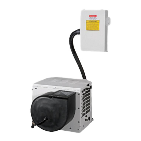
Marine Air Conditioner Installation & Operation Manual 2.Overview CONDENSER COIL FILTER ROTATABLE BLOWER MANUAL CONTROLLER EVAPORATOR ELECTRIC BOX DRAINAGE REVERSE VALVE ROTARY COMPRESSOR BASE/DRAIN PAN HANDLE HOW IT WORKS Your self-contained air conditioner consists of four main components and a refrigerant gas circulating through the system. -
Page 6: Installation
Marine Air Conditioner Installation & Operation Manual Model GIA-MAB-O-05Y01 91.5 GIA-MAB-O-09Y01 GIA-MAB-O-12Y01 119.4 GIA-MAB-O-16Y01 3.Installation 3.1 Unpacking and Inspection When the equipment is received, all items should be carefully checked according to the packing list to ensure all cartons have been received. Move units in the normal "up" orientation as indicated by the arrows on each carton. -
Page 7: The Size Of Sealed Room
Marine Air Conditioner Installation & Operation Manual DANGER:Electrical shock hazard. Disconnect voltage at main panel or power source before opening any cover. Failure to comply may result in injury or death. WARNING:This component does not meet federal requirements for ignition protection. Do not install in spaces containing gasoline engines, tanks, LPG/CPG cylinders, regulators, valves or fuel line fittings. - Page 8 Marine Air Conditioner Installation & Operation Manual The unit should be installed as low as possible, BUT NEVER IN THE BILGE OR ENGINE ROOM AREAS, ENSURE THAT THE SELECTED LOCATION IS SEALED FROM DIRECT ACCESS TO BILGE AND/OR ENGINE ROOM VAPORS. Installing the unit as low as possible (such as under a V-berth, dinette seat or bottom of a locker) and ducting the supply air as high as possible, creates an ideal airflow condition.
-
Page 9: The Water Inlet/Outlet Pipe
Marine Air Conditioner Installation & Operation Manual 3.5 The water inlet/outlet pipe Follow the steps below to connect the water inlet/outlet hose with the double-tube heat exchanger of units (1). Remove screws on the outer casing. (2). Remove the outer casing of the unit, and then connect the water inlet/outlet hose with the double-tube heat exchanger. -
Page 10: Condensate Drains
Marine Air Conditioner Installation & Operation Manual 3.6 Condensate Drains The condensate drain pan is 2” (50mm) high with two drain locations. During conditions of high humidity, condensate may be produced at a rate of approximately 1/2 gallon per hour (1.9 liters per hour). -
Page 11: Ducting
Marine Air Conditioner Installation & Operation Manual instructions. Model 5K(7K) Min. Return Air Grilles Size (re.) 48500mm 65680mm 76514mm 103584mm 3.10 Ducting Good airflow is critical for the performance of the entire system. The static pressure should not exceed 100 Pa.It is highly dependent on the quality of the ducting installation. The ducting should be run as straight, smooth and taut as possible minimizing the number of 90 degree bends (two tight 90°... - Page 12 Marine Air Conditioner Installation & Operation Manual pump from any foreign matter. Failure to install a seawater strainer will void the pump warranty. The seawater system should be installed with an upward incline from the speed scoop & seacock, through the strainer, to the inlet of the pump, next to the inlet of the a/c unit's condenser coil. The discharge from the a/c unit should run to the seawater outlet thru-hull fitting that should be located where it can be visually inspected for water flow as close to the waterline to reduce noise.
-
Page 13: Electrical Connections, Grounding And Bonding
Marine Air Conditioner Installation & Operation Manual 3.12 Electrical Connections, Grounding and Bonding All a/c units have a terminal strip mounted inside the electric box. The terminal strip is labeled for proper connections of the electrical supply, ground wires and pump circuits. A wiring diagram is provided in the electrical box and later in this manual. -
Page 14: Manual Controller Installation
Marine Air Conditioner Installation & Operation Manual standard E-8, or equivalent. (1). Connections between the vessel's AC system grounding conductor (green wire) and the vessel’s DC (Direct Current) negative or bonding system should be made as part of the vessel's wiring, per ABYC standard E-9, or equivalent. (2). -
Page 15: Electric Box Installation
Marine Air Conditioner Installation & Operation Manual 3.14 Electric Box Installation Mount the electric box using four M5 screws. Mount the electric box in a cool dry location and leave plenty of room for maintenance. 3.15 Installation Checklist (Review Prior To Installation) 3.15.1 Seawater cooling system: Speed scoop located as far below the water line and as close to the keel as possible ◆... -
Page 16: Wiring Diagrams
If the unit does not appear to be operating properly, refer to troubleshooting guidelines. ◆ Note: Do not turn the unit off and immediately turn it back on. Allow at least 30 seconds for refrigerant pressure equalization. 3.16 Wiring Diagrams WIRING DIAGRAM GIA-MAB-O-05Y01, GIA-MAB-O-09Y01 The specification of power cord is AWG14*3(3*1.5) -
Page 17: Operation
Marine Air Conditioner Installation & Operation Manual WIRING DIAGRAM GIA-MAB-O-12Y01, GIA-MAB-O-16Y01 The specification of power cord is AWG12*3(3*2.5) The diagram of power supply is below. Power Supply: 4.Operation 4.1 Manual Controller Operation CAUTION: Don't install the manual controller in a location where it can get wet. -
Page 18: Power On/Off
Marine Air Conditioner Installation & Operation Manual . Remote receiver . Fan control button . Digital display . Temp. Setting button (Increasing) . Fan speed display (HIGH-MID-LOW and AUTO speed) . Temp. Setting button (Decreasing) . Display of mode operation (COOL-DEHUMIDIFY-HEAT and . -
Page 19: Mode Setting
Marine Air Conditioner Installation & Operation Manual The setting range of temperature in each mode: ◆ COOL 61°F 86°F or 16°C 30°C DEHUMIDIFY 61°F 86°F or 16°C 30°C HEAT 61°F 86°F or 16°C 30°C In this mode, temperature cannot be changed. AUTO In this mode, temperature cannot be changed. -
Page 20: Key Lock
Marine Air Conditioner Installation & Operation Manual 4.8 Key Lock Press ▼and FAN key simultaneously, all keys are locked. Press ▼and FAN key ◆ simultaneously again, to unlock the keys. When keys are locked, the controller is locked out of system operation. “EE” will be displayed. ◆... -
Page 21: Accessories
Marine Air Conditioner Installation & Operation Manual it lights on. (2). After receiving the signal from remote controller, the display of temperature on the manual controller will light on; meanwhile, the unit carries out corresponding operation. 1). After the unit stops, there is no display on the manual controller. 2). -
Page 22: Button / Function And Description (Cover Closed)
Marine Air Conditioner Installation & Operation Manual 5.2 Button / Function and Description (Cover Closed) SWING button FAN button Note: there is no swing Press this button to change function in this A/C unit. the fan speed of: OPER TEMP button TEMP. -
Page 23: Button / Function And Description (Cover Open)
Marine Air Conditioner Installation & Operation Manual 5.3 Button / Function and Description (Cover Open) OPER Liquid crystal display It shows all the setting contents Note: Cover remove will not change the display contents. MODE ON/OFF 5.4 COOL Mode Operation According to the difference between room temperature and set temperature, the ◆... -
Page 24: Battery Replacement In Remote Controller
Marine Air Conditioner Installation & Operation Manual Temperature cannot be set in this operation mode. ◆ 5.8 Battery Replacement in Remote Controller Remote controller battery requirements: Two AAA alkaline cells. (1). Slide the cell cover downward to take out the worn cells. Replace the worn cells. (Note to the correct polarity). -
Page 25: Troubleshooting
Marine Air Conditioner Installation & Operation Manual 6.Troubleshooting FAULT POSSIBLE REASON CORRECTION Turn circuit breaker on at ship's panel, A/C circuit breaker is off See control operation section in this manual. Display control is not turned on. Check wiring Diagram and correct if necessary. Fuse is broken Replaced with a new fuse. - Page 26 Marine Air Conditioner Installation & Operation Manual Continued: FAULT POSSIBLE REASON CORRECTION Remove any obstructions in return air stream, Air flow is blocked Clean return air filter and grille. Check for Low air flow crushed or restricted ducting, ducting must be as straight, smooth and taut as possible.
-
Page 27: Maintenance
Marine Air Conditioner Installation & Operation Manual 7.Maintenance 7.1 Reversing Valves Reverse cycle units have a reversing valve; the valve must be energized periodically to keep the internal parts moving freely. To do this, switch the a/c unit into heat for a few seconds once a month. - Page 28 Marine Air Conditioner Installation & Operation Manual various methods employed using a 50/50 non-polluting biodegradable anti-freeze/water solution. Any method that causes the anti-freeze solution to flow downward is the method of choice. By this, the anti-freeze solution will displace any water trapped and eliminate the possibility of freezing in hidden areas.
- Page 29 C./ Industria, 13 l Polígono Industrial El Pedregar 08160 Montmeló Barcelona (Spain) Phone: (0034) 93 390 42 20 Fax: (0034) 93 390 42 05 info@giatsu.com www.giatsu.com...
Need help?
Do you have a question about the Giatsu GIA-MAB-O-05Y01 and is the answer not in the manual?
Questions and answers